62
BIFFI FAIL SAFE ELECTRIC ACTUATORS, MODEL EFS2000V4
InstructIon and operatIng Manual
17.5.7 Excessive torque for valve operation
- Clean, lubricate and check the valve stem.
- Valve packing too tight: loosen the gland bolt
nuts.
- Coupling type ‘A’: tight fit between bush and
stem: increase the thread clearance on the
drive coupling.
- Coupling types ‘B1’, ‘B2’, ‘B3’ and ‘B4’:
ensure there are no axial forces on the valve
stem by leaving an adequate axial clearance
between the stem and the drive bush. Also
check that all transmission shafts, universal
joints or bulkhead passages have sufficient
lubrication and check that the transmission
shafts are not bent.
- Check that the internal valve trim or the
reducer gears are well lubricated and not
damaged.
- Check the alphanumeric display for
diagnostic messages, and proceed with the
suitable corrective actions as described in
chapter 17.5.11.
17.5.8 The actuator does not stop in fully open or
fully closed position
- Check that the actual open and close
positions of the valve respectively correspond
to 100% and 0% on the actuator display
- Make sure that the torque and travel limits
are correctly set (see ‘Set-up routines,
actuator setup, set stroke limits’).
17.5.9 The numeric position display indicates ‘E01’
- It is necessary to re-calibrate the stroke
limits (see ‘Set-up routines, actuator setup,
set stroke limits’).
Off
Yes
Yes
Yes
Yes
No
No
No
No
No
No
No
No
Yes
Yes
Yes
Yes
Yes
Yes
Local
Remote
3-position
selector
View
variables
Display
XXXXXX XXXXXX
XXXXXX NEXT?
ALARMS
VIEW?
ALARM II- I
NEXT?
ALARM II- N
NEXT?
RESET
OK?
RESET
OK?
WARNING II- N
NEXT?
WARNING II- 1
NEXT?
WARNINGS
VIEW?
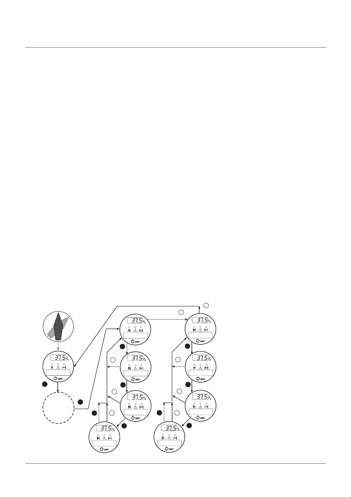
17.5.10 Diagnostic messages
The alarm and warning lists contain the
alarms and warnings momentarily present.
Warning is the condition that occurs when a
variable reaches a critical value and/or when a
maintenance action is required, but all actuator
functions are still available. The flashing of
the alarm/warning LED indicates a warning
condition. Alarm is the condition that occurs
when a variable is outside the acceptable range
and some actuator function is not available. If
the alarm/warning LED is on there is an alarm
condition. When the fault condition disappears,
the corresponding alarm or warning also
disappears from the list. A reset routine is
provided to clear the types of alarms and
warnings that are memorized (over-torque,
jammed valve, etc.).
View procedure
• Move the 3-position selector to either OFF or
REMOTE, and then press NO to scroll through
the list of available variables.
• Press YES when the display shows message
‘ALARMS view?’ Press YES to scroll through
the list of alarms.
• Press NO when the display shows message
‘ALARMS view?’.
• Press YES when the display shows message
‘WARNINGS view?’ Press YES to scroll
through the list of warnings.
• Press YES to reset the alarms or warnings
with memory.