BA-EN-HydroStar V3.1 page 16
7 Control unit
• Observe DIN VDE 0100-702 (Installation of low voltage systems, Section 702: Swimming
pools and other pools).
• The control unit must be installed in area 2 as per DIN VDE 0100-702. The power lead-in must be
equipped with residual current protection (RCD) with a rated residual operating current of ≤ 30mA.
• The system must have a 16 A inert fuse installed.
• Installation in a dry room in which other technical equipment for operating the swimming pool is
installed. The room should be a maximum of 10 m from the pool.
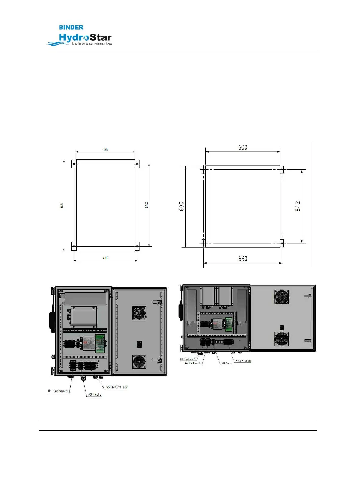
• The control unit is designed for wall mounting. It is mounted with 4 screws Ø 8 mm (not included in
delivery). It must be fixed in such a way that the cable entries are on the bottom.
Mounting BGA 160/215/275
Mounting BGA 320/430/550
HydroStar BGA 160/215/275
HydroStar BGA 320/430/550
NOTE Please also observe the circuit diagrams included in delivery!