Repair work at the cooling system
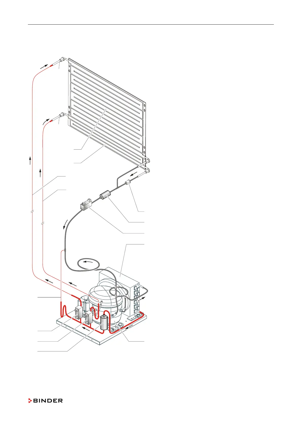
10.7 Overview cooling cycle
A Solenoid valve (-7Y2)
B Solenoid valve (-7Y1)
C Filter dryer (-1J1)
D Compressor (-6M1)
E Condenser (-6M2)
F Solenoid valve (-7Y3)
G Filter (-1J6)
H Reflux valve (-1J7)
I Capillary tube (-1J3)
J Capillary tube (-1J2)
K Evaporator plate, small (-1J5)
L Evaporator plate, large (-1J5)
M Capillary tube (-1J4)
a Injection point cooling
b Injection point dehumidification
Figure 59: Cooling cycle
Service Manual KBF (E5.2) 04-2015 119