Repair work at the inner and outer chamber
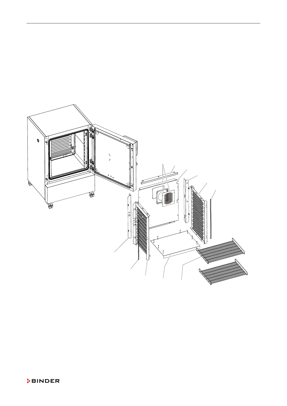
7. Die side plates (C, G) are screwed with cap nuts at the stud bolts at the inner chamber ceiling.
Incline the side plates (C, G) with the lower edge to the inside, pull them forward and remove the
parts.
8. Remove the gaskets between the inner and the outer chamber (B, F)
9. Unscrew the screws of the rear panel of inner chamber (I) and remove the panel.
10. Install the inner chamber by following steps 1 to 11 in reverse order. When replacing the inner
chamber side plates (C, G), we recommend replacing the gaskets between the inner and the
outer chamber (B, F) as well.
Figure
27: Replacing the inner chamber and the gaskets between the inner and the outer chamber
G Inner chamber side plate, right
B Gasket between the inner and the outer chamber
C Inner chamber side plate, left
I Inner chamber rear panel
F Gasket between the inner and the outer chamber
Service Manual KBF (E5.2) 04-2015 65