EasyManuals Logo

Bio-Logic SP-240 User Manual

Default Icon
122 pages
To Next Page IconTo Next Page
To Previous Page IconTo Previous Page
Page #104 background imageLoading...
Page #104 background image
Manual for VMP300-based instruments
96
Input impedance
1 ΙΙ 25 pF typical
Input Bias current
< 10 pA
Bandwidth (-3 dB)
8 MHz
Common mode rejection ratio
> 60 dB at 100 kHz
Ground to chassis impedance
Floating mode
1 ΙΙ 25 pF typical
Grounded mode
< 100 Ω
IR compensation
Resistance determination
EIS
Compensation mode
Hardware or software positive feedback
Compensation range
Programmable from 0 to 100 % of the current range
resistor
Auxiliary Inputs/outputs
External Input
Can be used to apply an external waveform directly to
the control amplifier
2 Analog Inputs
Automatic ± 2.5 V, ± 5 V, ± 10 V ranges - 16 bits
resolution
1 Analog Output
16 bits resolution on the ± 10 V range
2 Digital Inputs
TTL level Trigger input and Open input
1 Digital Output
TTL level Trigger output
2 Monitor Outputs
Cell current and compensated working electrode
potential
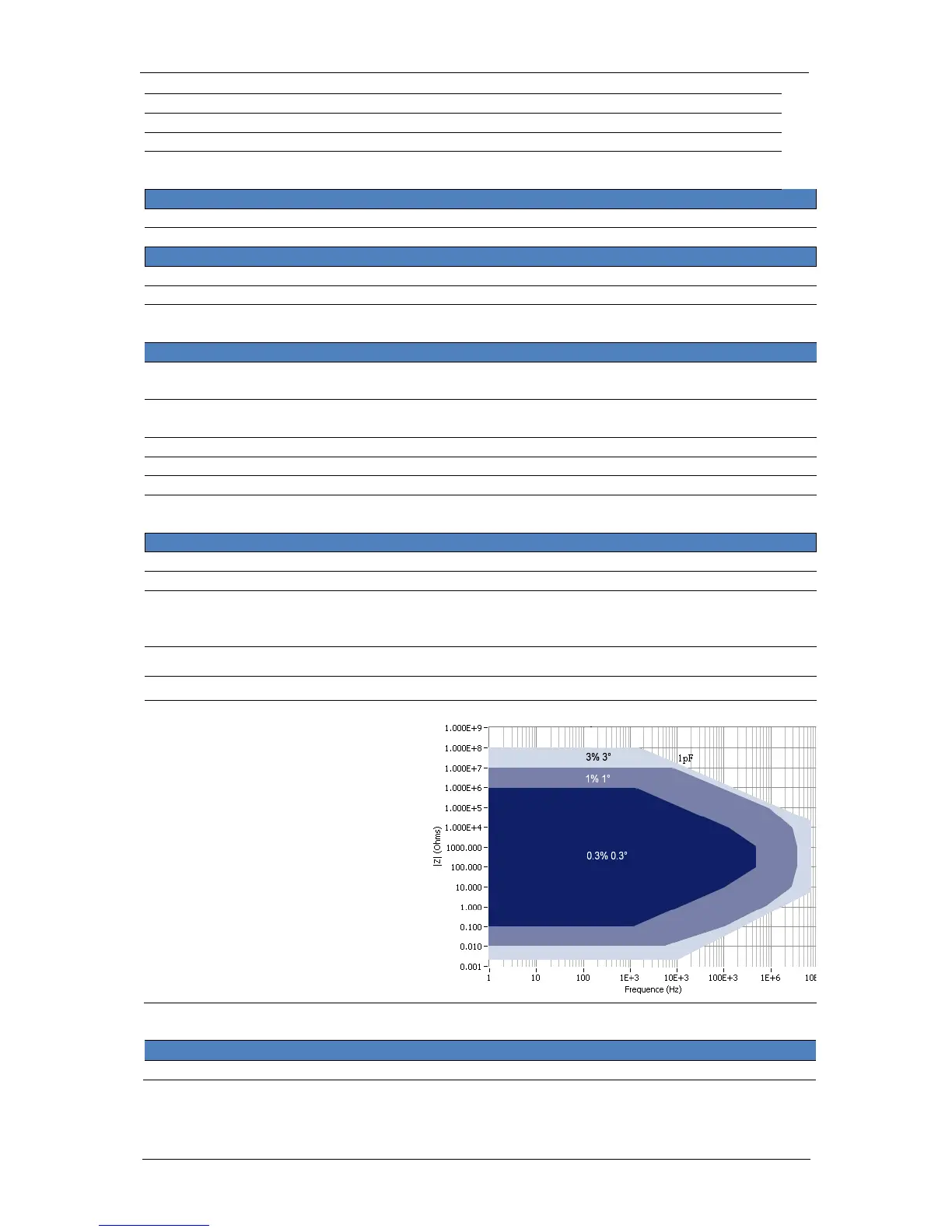
Impedance specifications (EIS option only)
Frequency range
10 µHz to 7 MHz
Frequency resolution
< 10 ppm of the setting
Sinus amplitude
0.5 mV to 5 V with 76 µV resolution
0.1 % to 100 % of the current range with resolution of
0.004 % of the range
Accuracy
See contour plot
Mode
Single sine, Multisine, FFT analysis
Contour plot
10.2.2 Ultra Low Current
Cell Control
Maximum Current
± 500 mA (± 1 A continuous with 1 A/48 V)

Table of Contents

Questions and Answers:

Question and Answer IconNeed help?

Do you have a question about the Bio-Logic SP-240 and is the answer not in the manual?

Bio-Logic SP-240 Specifications

General IconGeneral
BrandBio-Logic
ModelSP-240
CategoryMeasuring Instruments
LanguageEnglish

Related product manuals