49
5.3.2 Connection to the cell with 2A/30V, 4A/14V and with 10A/5V boosters
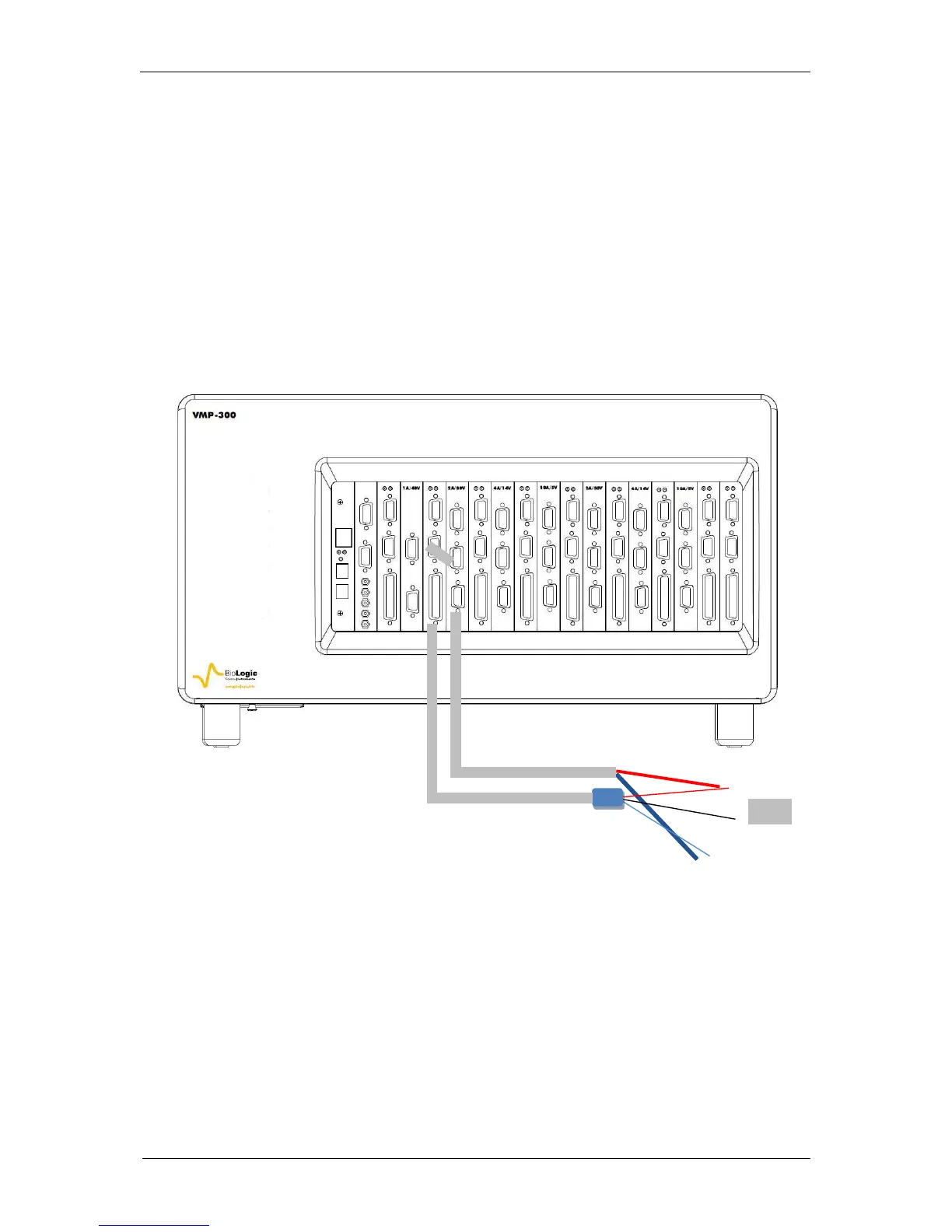
With the 2A/30V, 4 A/14 V and 10A/5V boosters, the connection with the cell cable of the
potentiostat/galvanostat board remains the same, but the P1 and P2 (4 mm) leads coming
from the booster board have also to be connected to the cell. The booster board needs to be
connected to the channel board using the DB15 connection cable.
The 2A/30V, 4A/14V and 10A/5V boosters can be connected in parallel, so it is possible to
increase the current ability of the channel board by using in parallel numerous 2 A, 4 A or 10A
boosters. For example, if 12 boosters of 10A are connected to one potentiostat/galvanostat
board, user can reach a current of 120 A.
Limit of instrument configuration:
VSP-300 chassis accepts a maximum of 4 booster boards and these boosters have to
be inserted in the slots #1 to #4 (not #5 and #6).
Because of power limitation, VMP-300 chassis accepts a maximum of 12 booster boards
if powered with 110Vac electrical network. They can be inserted in any slot.
Fig. 69: Channel board connection to the cell with one 2A/30V booster.