EasyManuals Logo

Bio-Logic SP-240 User Manual

Default Icon
122 pages
To Next Page IconTo Next Page
To Previous Page IconTo Previous Page
Page #79 background imageLoading...
Page #79 background image
Manual for VMP300-based instruments
71
Fig. 99: Dummy Cell-2
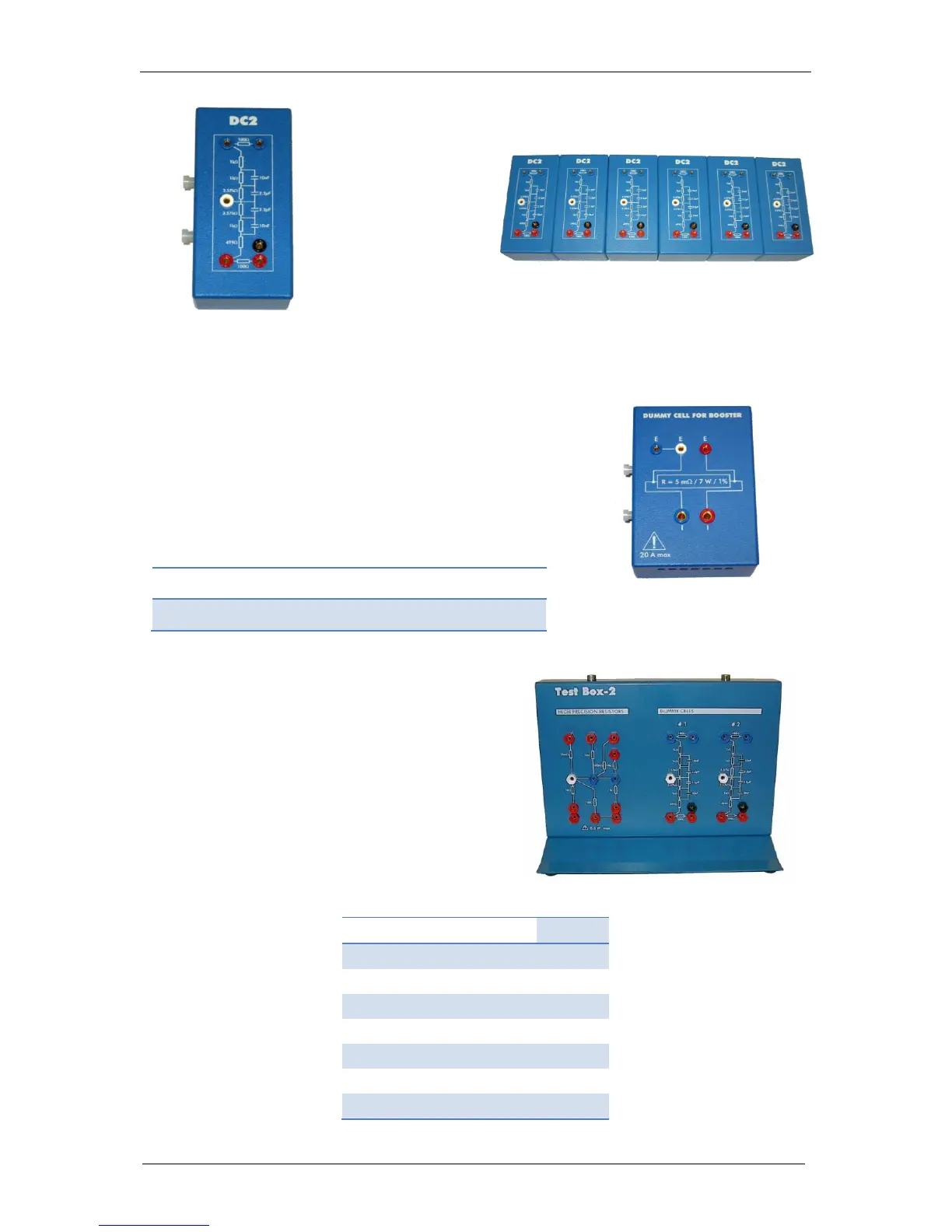
7.5.2 Dummy cell for booster
The Dummy cell for booster is specifically dedicated to
periodically check a booster. The dummy cell for booster
is provided with each booster chassis.
Dummy cell for booster and DC2 can be bound together
as well.
Characteristics of the dummy cell are given in the
following table:
Resistance
Tolerance
Temp.
coeff.
Current
Max
Power
Max
5 mΩ
1%
+/- 50
ppm/°C
20 A
7 W
Fig. 100: Dummy Cell for Booster.
7.5.3 Test Box 2
The Test Box 2 is a tool specifically designed for
checking the calibration of the standard channel
boards of our instruments. This test box is made
of one electrical circuit with high precision resistors
for calibration check and two dummy cell circuits
for user training. The high precision resistor circuit
is made with 7 resistors, one to check each current
range of the board.
Fig. 101: Test Box-2.
High precision resistor characteristics:
High precision resistor
I range
10 Ohms +/- 0.04%
1 A
100 Ohms +/- 0.02%
100 mA
1 kOhms +/- 0.02%
10 mA
10 kOhms +/- 0.02%
1 mA
100 kOhms +/- 0.02%
100 µA
1 MOhms +/- 0.02%
10µA
10 MOhms +/- 0.04%
1 µA

Table of Contents

Questions and Answers:

Question and Answer IconNeed help?

Do you have a question about the Bio-Logic SP-240 and is the answer not in the manual?

Bio-Logic SP-240 Specifications

General IconGeneral
BrandBio-Logic
ModelSP-240
CategoryMeasuring Instruments
LanguageEnglish

Related product manuals