41
5. Connection to the cell
To connect the instrument to your experiment (the “cell”) a cell cable is used. The connection
of the cell cable to the instrument varies depending on whether or not a current booster or low
current option is to be used. Section 6.1 describes the various ways in which the cell cable
can be connected to the instrument. Section 6.2 describes the various ways in which the cell
cable can be connected to the experiment, depending on the type of system you have (e.g.,
battery, 3-electrode electrochemical cell, etc.) and the information you wish to obtain.
5.1 Cell cable to the instrument
5.1.1 Cell cable and potentiostat/galvanostat board association
To keep the high end specifications especially for EIS measurement, the cable and board are
calibrated together, so user has to use the boards with the associated cable (same serial
number).
When potentiostat/galvanostat board(s) is (are) purchased with the chassis, each cable has a
label indicating the channel number i.e. the number of the slot where the
potentiostat/galvanostat board is inserted.
If additional boards are purchased afterwards, user has to plug the appropriate cable to board.
The serial number indicated on the electrometer (blue box) are the same as the serial number
indicated on the label stick on the board. Note for ULC cable, the boards, the cable and the
electrometer have to have the same serial number.
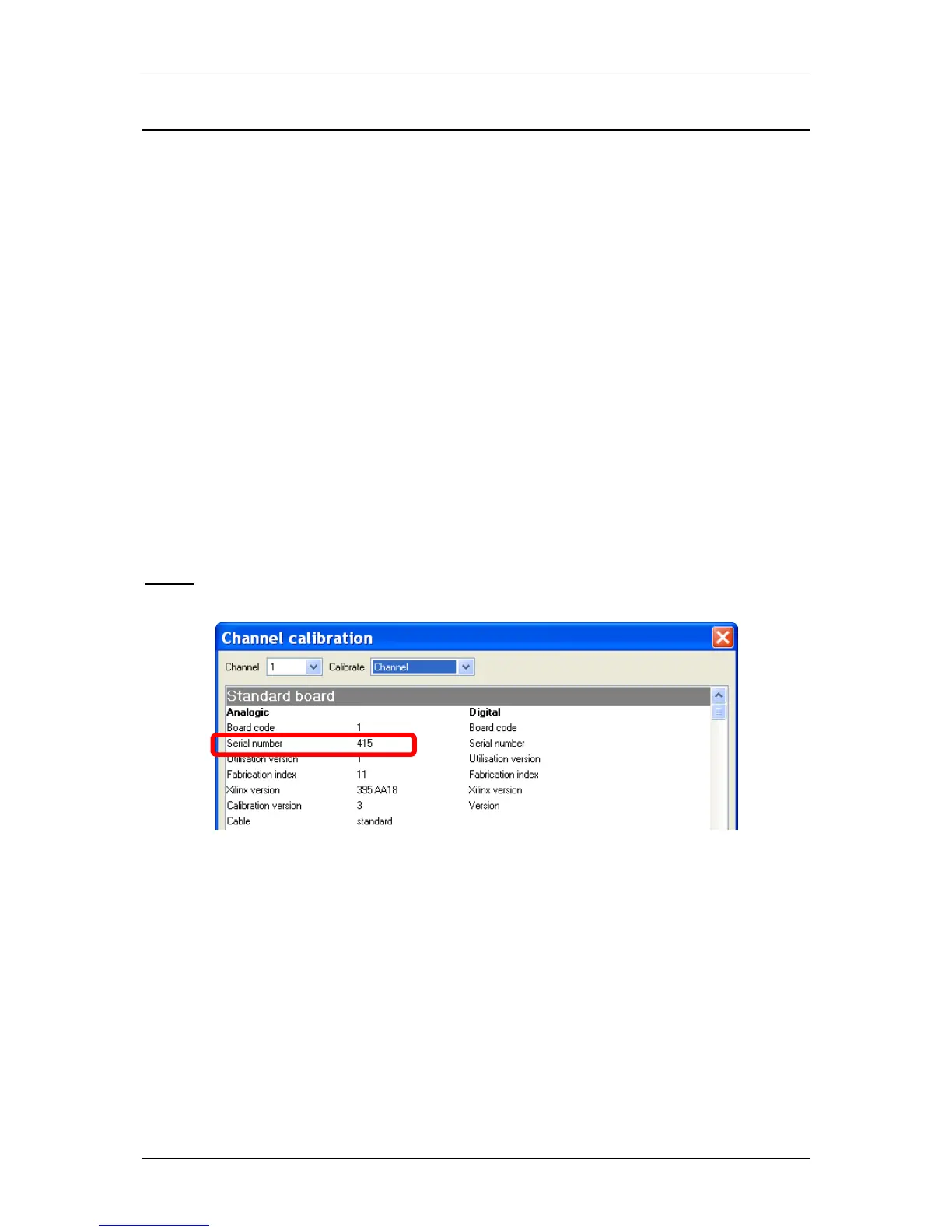
NOTE:
When the board is plugged into the chassis, it is possible to get the serial number of the board
by using the calibration tool (more info on the calibration routine at the end of the manual).
Fig. 54: Serial number information via the “Channel calibration” procedure.
5.1.2 Boards description
Each board has several connectors on the front panel but each board has been designed to
avoid any confusion (different types and different genders for each connector).
5.1.2.1 Potentiostat/galvanostat/ZRA board
Three connectors are available on the front panel of the potentiostat/galvanostat/ZRA board:
DB-9 connector for auxiliary analog/digital signals and to connect to the calibration
board,
DB-15 connector for the connection to the calibration board,
Sub mixed DB-25 connector to be connected to the cell cable (standard cable or ULC
cable).