Up to five current boosters can be
connected in parallel, increasing the
maximum current that can be passed
through the cell. In order to simplify the
connections, a current collector was
designed (Fig. 95). A maximum current
of 60 A can flow through the CC5
(Current Collector for 5 boosters).
This simple device collects the current
coming from each booster in parallel
and delivers it through two 60 cm power
cables terminated by two sturdy
crocodile copper clips, similar to
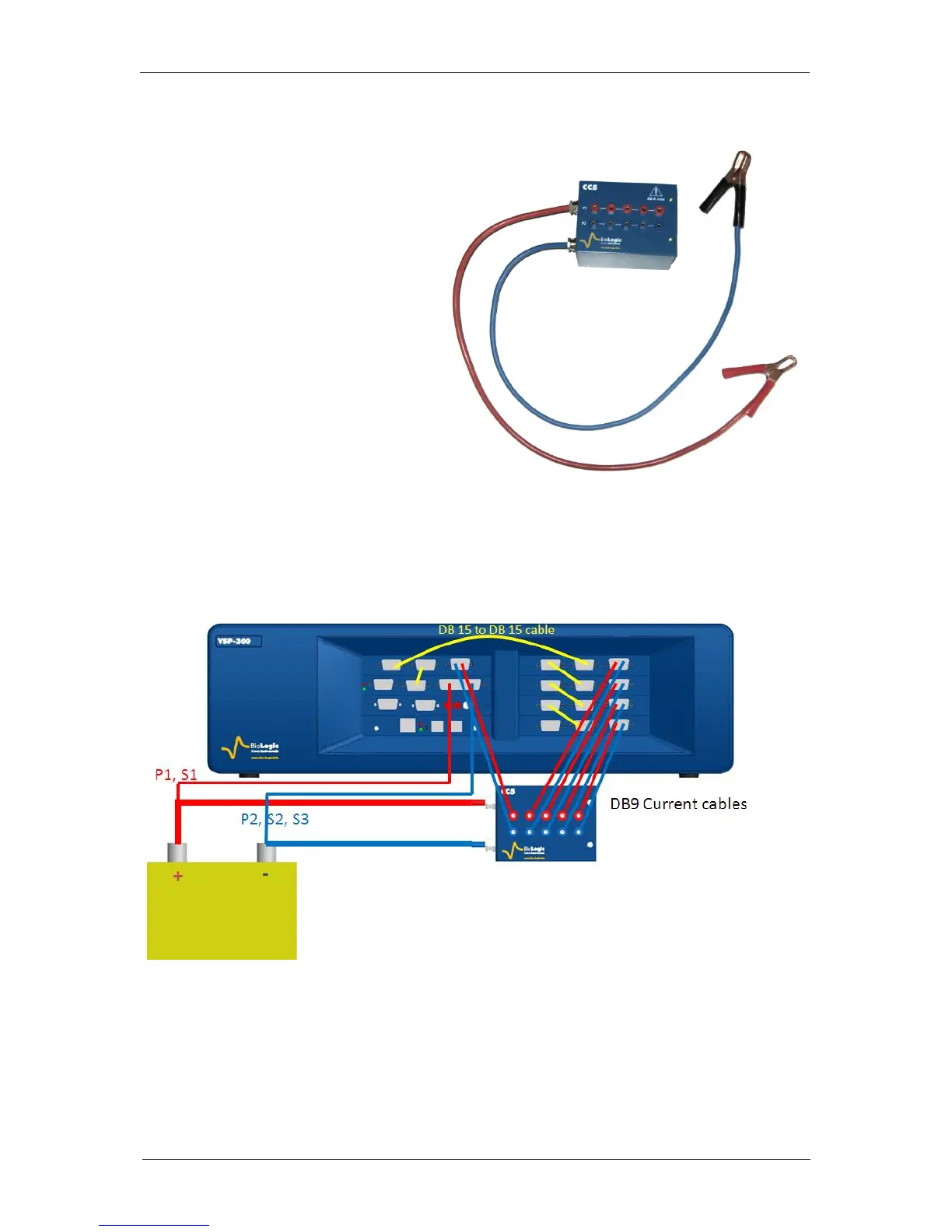
automobile battery clips. The scheme
below (Fig. 96) shows how to connect in
parallel five boosters inserted in the
VSP-300 chassis. All the boosters need
to be connected to each other using the
DB 15 connectors.
On each booster the power cables are connected to the CC5 as it is shown in Fig. 99 below.
The crocodile clips of the CC5 are then clipped to the battery or the cell of interest. The total
current will flow through these cables. The connection leads from the potentiostat board
coming from the DB 25 connector, are connected directly to the battery.
Fig. 96: Connection of horizontal VSP-300 and CC5 to a battery