Manual for VMP300-based instruments
10
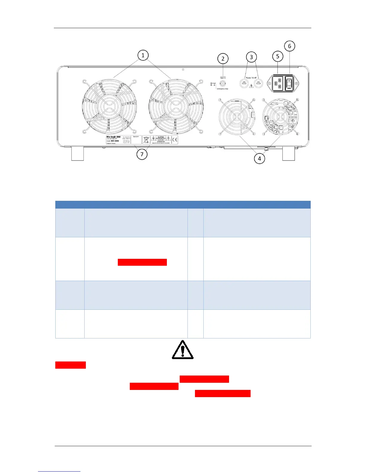
Fig. 6: HCV-3048 back panel.
Table 3: Description of the components of the back panel of the HCV-3048.
Rear ventilation grids for heat
sink
This is where the air and heat will
come out.
Power socket
Standard C19 socket to power the
booster.
Open In
It is a high impedance BNC input
that can be remotely accessed to
trigger the Emergency Stop. It will
open the relays of the power circuit.
The Status LED will turn red.
Fuses 2 x 16 AF
This is where the protection fuses
are located. Each is a 16 A Fast
fuse.
The back panel also features
additional safety information as well
as the serial number of the
instrument.
Rear ventilation grids for power
supply
This is where the air and heat from
the power supply will come out.
WARNING
1) When HCV-3048 are in parallel, the BNC Open In inputs must also be connected such that
all boosters stop at the same time when the Emergency Stop button is pushed or when an
external device triggers an Emergency Stop via Open In.
2) This is a high input impedance as long as the Emergency Button is not pushed. If it is
pushed with a connected instrument, the outer conductor of the BNC connector will be shorted
to Ground and can damage the output of the connected instrument.