51
.The current to the cell is provided by the booster using two 10 mm
2
highly flexible Cu-leads
with silicone insulation with 6 mm safety sockets and plugs with snap-in lock at both ends that
fit into the 6 mm safety flush-mounting receptacles with snap-in lock on the front panel of the
HCV-3048.
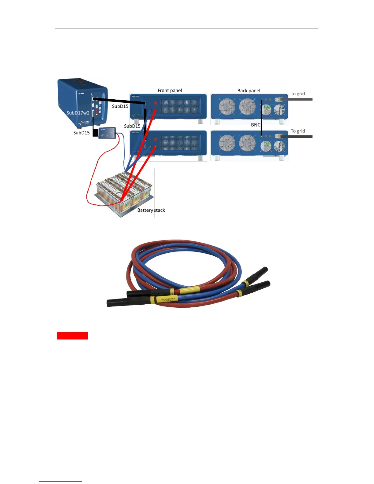
Fig. 72: Connection of the pstat to the HCV-3048 boosters and cells
Fig. 73: HCV-3048 2.5 m standard power cables with 6 mm safety sockets.
WARNING
It must be ensured when using boosters in parallel that the BNC cables in the back of the
instruments are also connected, such that when the emergency stop is triggered, either by
pushing on the front panel button or by a logic signal (TTL) coming from an external device.
When using several boosters, the power cables are all connected to the same point on the
stack, as well as the voltage measurement/control.
As the maximum power per booster can reach 2 kW, each HCV-3048 must be connected to
one separate power grid socket.
Please be aware of the following limitations for the voltage measurement leads (HV-48)
and the power cables or current measurement/control leads (HCV-3048).