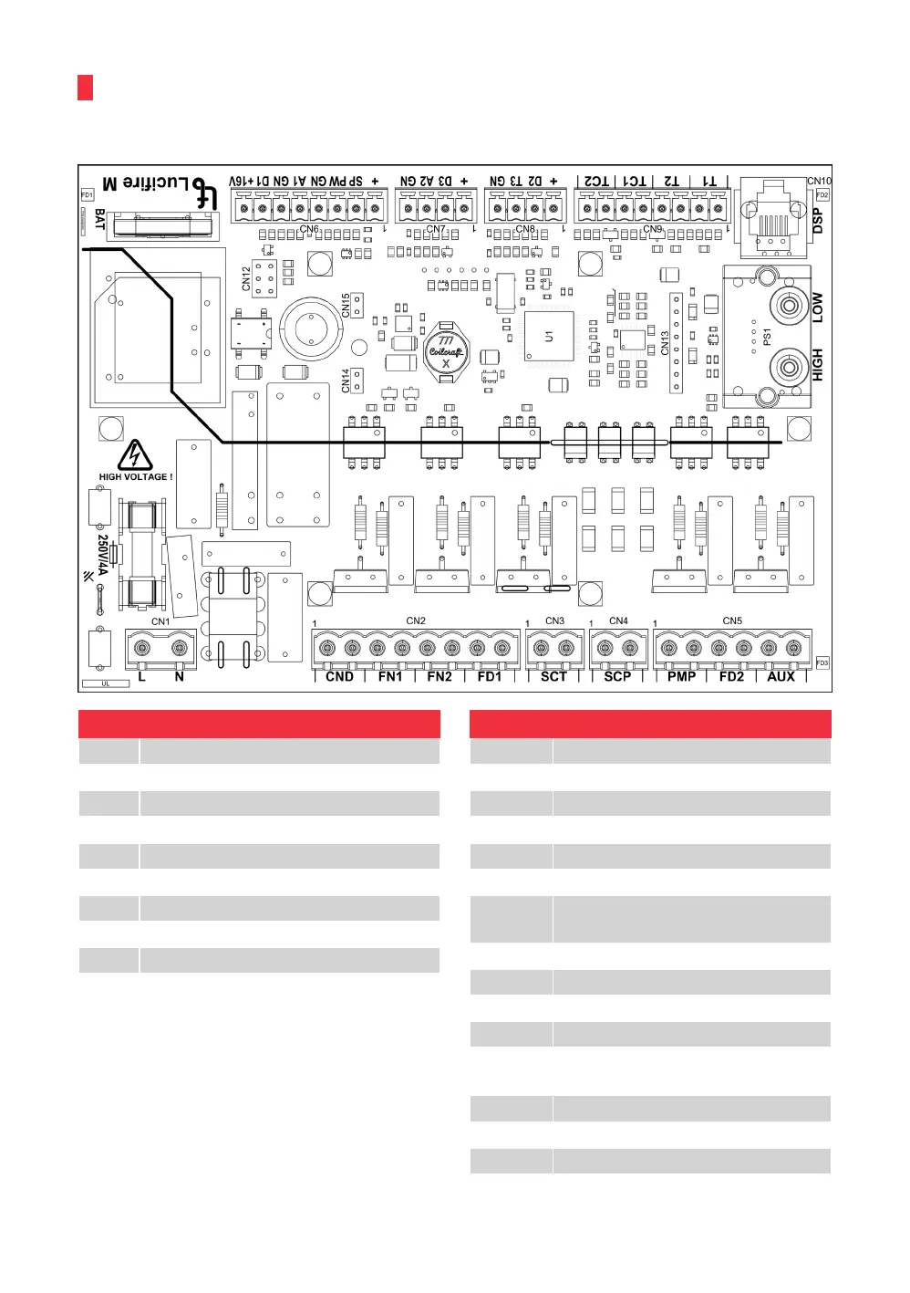
12. ELECTRICAL WIRING DIAGRAM
IQ1 - Lucifire
Connector - 220V
CND Igniter
FN1 Fan - intake
FN2 Fan - chimney
FD1 Pellet feeder - wormdrive
SCT STB safety thermostat
SCP Pressure switch - safety1/3
PMP Boiler pump
FD2 Firebox cleaning
AUX Turbulator cleaning
*IQ2 - Not in use / connect to IQ2
Connector - Sensors
T1 Boiler water temperature
T2 Return water temperature
TC1 Flue gas temperature
TC2 Firebox temperature
D2 / GN DHW thermostat -IQ2 *
T3 / + Buffer below - IQ2*
D3 / GN Room thermostat /
external boiler control
A2 / + Buffer above - IQ2*
SP
PW / GN PWM - boiler pump
A1 / GN Pressure sensor [+ 16VA1 GN]
D1 / GN Firebox cleaning
- rev counter
+16V + 16V Pressure sensor
DSP Display / table
HIGH pneumatic connection
LOW pneumatic connection
www.biodom27.si
38 BIODOM 27A