68
english
4.5 Return valve
If a return valve has been installed, the pump has to be set up
(see point 7.2) so that the pump’s minimum delivery pressure
can exceed the valve’s closing pressure at any time.
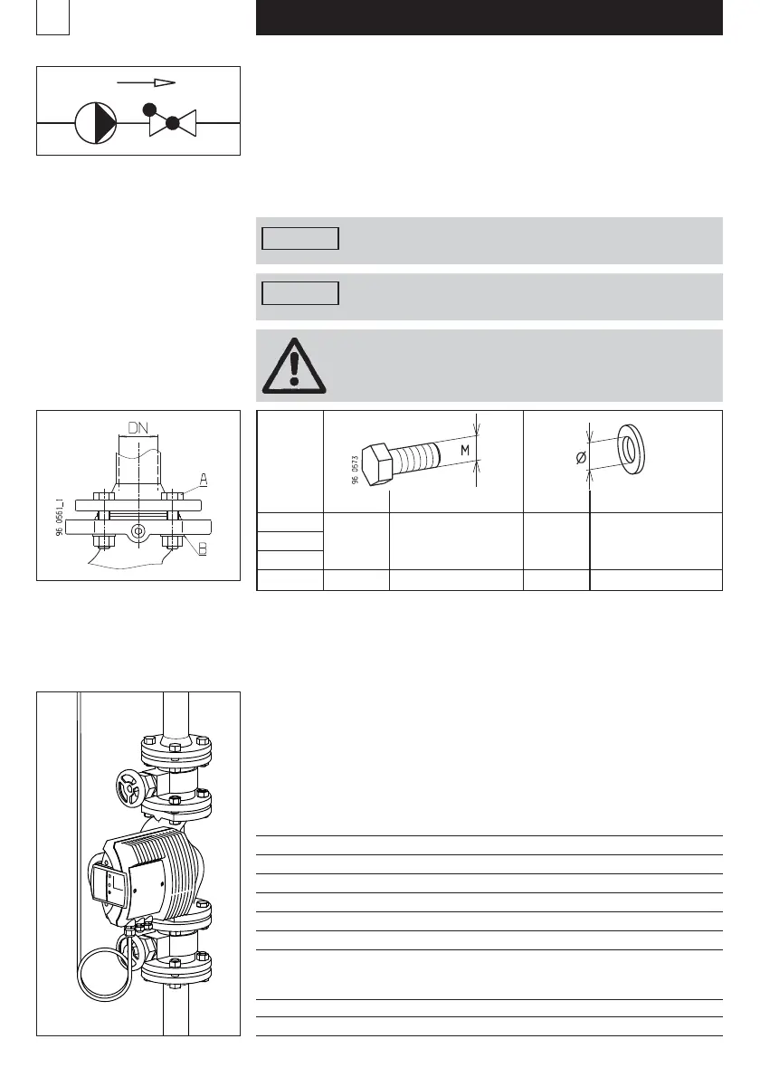
4.6 Flange connection
The pump flanges are bored with fixing holes PN6 / PN10 / PN16.
The plain washers «B» provided are to be installed
on the pump side to ensure that the flanges are securely fastened.
Admissible screw torque:
for M 12 <40 Nm
for M 16 <95 Nm
The installation of combination flange
with combination flange is not admissible.
4.7 Minimum pressure
The minimum pressure in the pump connection at 75 °C
to ensure lubrication of the friction bearings:
Single pumps Twin pumps
A 402/402-1 V2, AW 402-1 V2 AD 402-1 V2 0,4 bar overpressure
A 501 V2 AD 501 V2 0,2 bar overpressure
A 502 V2 AD 502 V2 0,2 bar overpressure
A 651 V2, A 651-1 V2 AD 651 V2 0,35 bar overpressure
A 652 V2 AD 652 V2 0,35 bar overpressure
A 801 V2 0,35 bar overpressure
The values apply up to 500 m above sea level.
Additions for higher altitudes:
0.01 bar per 100 m of altitude
Addition for: 95 °C + 0,45 bar
Addition for: 110 °C + 1,10 bar
Install the sluice gate before and after the pump.
This prevents the fluid from being drained and refilled
when the pump is exchanged.
Use the appropriate screws
for the given nominal pressure PN.
Safety elements (such as spring lock washers)
are not admissible.
Warning
Special seals and screws must be used
for PN 10/16.
Warning
PN 6 PN 10 / PN 16 PN 6 PN 10 / PN 16
DN 40
DN 50 M 12 M 16 Ø 14 Ø 18
DN 65
DN 80 M 16 M 16 – –
A B
 Loading...