KW-231-110
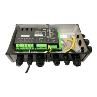
3.8 Screwing the cover onto the module housing
• Attach the enclosed adhesive label "CM-
RC-01" into the cover of the terminal box.
• Then screw the protective earth conductor to
the terminal box cover.
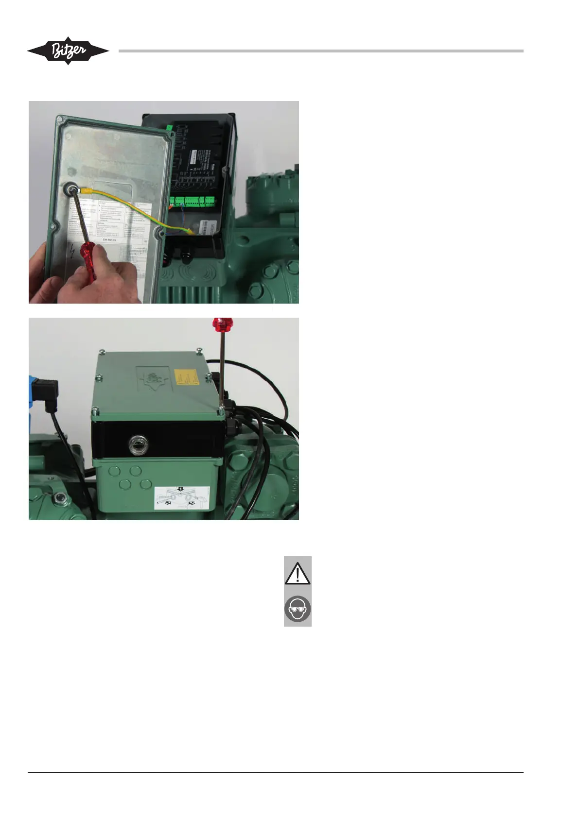
• Put the terminal box cover on the compressor
module housing and fasten it using the 6 en-
closed screws (M5 x 70 mm).
4 Mounting the optional CM-RC-01 extension kits
Required components and procedure to follow for
mounting the optional extension kits of the compressor
module add-on kit:
• Mounting and connecting valve flanges and solenoid
valves for capacity control (CRII) and/or start unload-
ing (SU).
• Mounting and connecting the pressure transmitters.
• Mounting and connecting the liquid injection.
• Mounting and connecting the additional fan.
WARNING
The compressor is under pressure!
Serious injuries are possible.
Depressurize the compressor!
Wear safety goggles!
After mounting new components such as discharge gas
temperature sensor, injection nozzle or injection valve: