KW-231-1 9
3.6 Further electrical connections on the CM-RC-01
• Voltage supply of the compressor module on ter-
minal strip CN1 (115 .. 230V +10%/-15%, 50/60Hz)
– Terminal 1: L
– Terminal 2: N
• Command for compressor start (release signal from
system controller).
• Analogue signal for capacity control from the system
controller (0 .. 10 V).
Schematic wiring diagram and further information, see
Technical Information KT-230.
3.7 Laying the cables
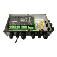
4-cylinder compressors 4JE-13Y .. 4FE-35(Y):
• Lay the cables along the cable holders and
use cable ties to fix them.
The figure shows the compressor with compon-
ents of the optional extension kits.
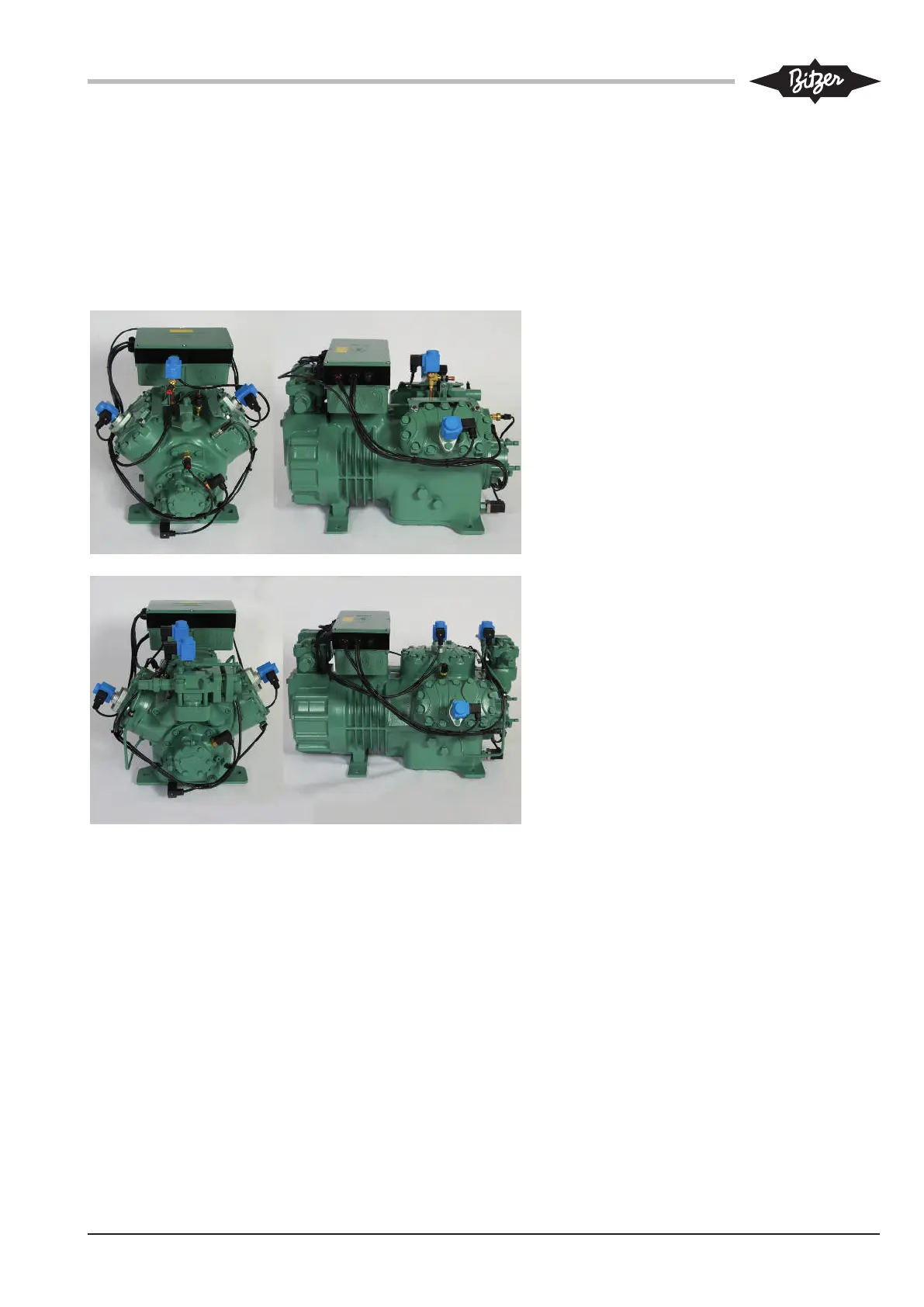
6-cylinder compressors 6JE-22Y .. 6FE-50(Y):
• Lay the cables along the cable holders and
use cable ties to fix them.
The figure shows the compressor with compon-
ents of the optional extension kits.