KW-231-112
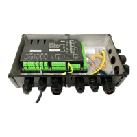
• Shorten the cables as needed, pass them
through the cable glands on the compressor
module into the module housing and connect
them to the CN6 terminal strip.
If no additional extension kits are mounted:
• Proceed with the other electrical connections on the
CM-RC-01 (see chapter Further electrical connec-
tions on the CM-RC-01, page 9).
• Lay the cables and close the cable ties (see chapter
Laying the cables, page 9).
• Screw the protective earth conductor onto the ter-
minal box cover and attach the cover to the module
housing (see chapter Screwing the cover onto the
module housing, page 10).
4.2 Mounting the "Pressure transmitter" extension kit
NOTICE
The two pressure transmitters must not be inter-
changed. They differ by the component number
engraved in the component:
High pressure transmitter: 2CP5-71-47.
Low pressure transmitter: 2CP5-71-49.
Information
Alternative mounting position for discharge gas
temperatures exceeding 135°C:
Connect the pressure transmitters to the dis-
charge gas line, as close as possible to the
valves using one refrigerant hose each. Length
of the refrigerant hose: at least 200 mm to avoid
overheating of the transmitter.
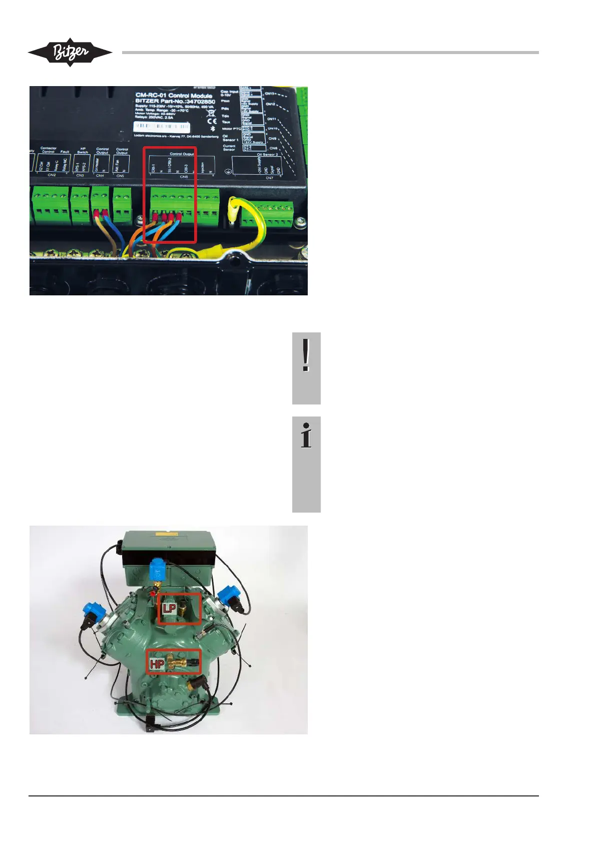
4-cylinder compressors 4JE-13Y .. 4FE-35(Y):
• Remove the sealing plugs from the connect-
ors marked by rectangles and clean the
threaded bores.
• Screw the enclosed screwed nipple (low pres-
sure transmitter) resp. T-piece (high pressure
transmitter) with Schrader valves into the
threaded bores.
• Then screw the high pressure transmitter
(2CP5-71-47) into place at the HP position
and the low pressure transmitter
(2CP5-71-49) at the LP position (tightening
torque 35-40 Nm). Do not insert a blanking
plate between screwed nipple and pressure
transmitter, since this will prevent the
Schrader valve from opening!