KW-231-116
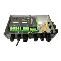
• Shorten the cables as needed, pass them
through the cable glands on the compressor
module into the module housing and connect
them to the CN6 terminal strip.
If no additional extension kits are mounted:
• Proceed with the other electrical connections on the
CM-RC-01 (see chapter Further electrical connec-
tions on the CM-RC-01, page 9).
• Lay the cables and close the cable ties (see chapter
Laying the cables, page 9).
• Screw the protective earth conductor onto the ter-
minal box cover and attach the cover to the module
housing (see chapter Screwing the cover onto the
module housing, page 10).
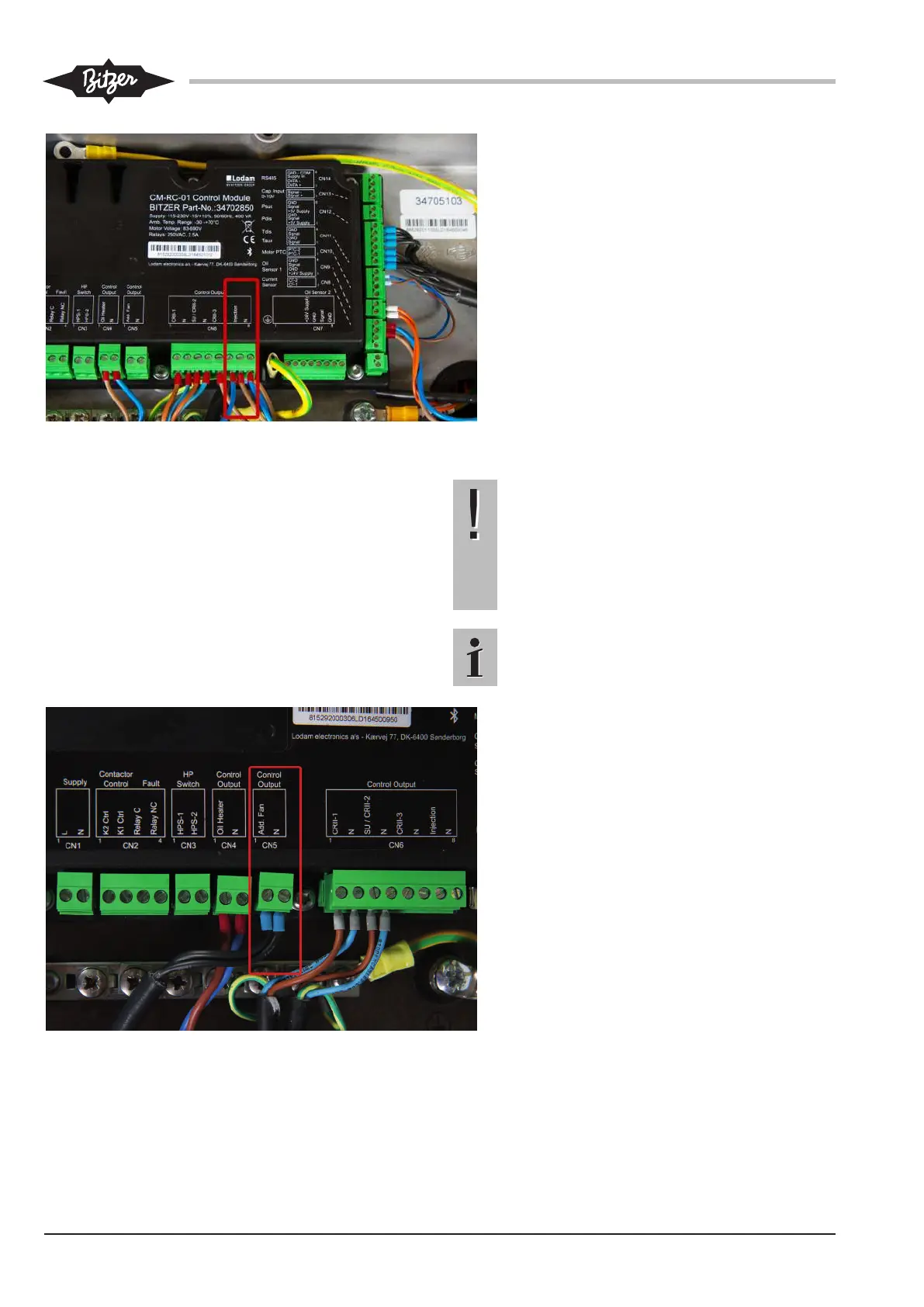
4.4 Mounting the "Additional fan" extension kit
NOTICE
When mounted, the additional fan hides the lift-
ing eyes of the compressor!
The lifting eyes cannot be used for lifting the
compressor when the additional fan is installed.
Do not mount the additional fan before installing
the compressor in the system!
Information
For details, see Technical Information KT-140.
• Pass the cables through the cable glands on
the compressor module into the module hous-
ing and connect them to the CN5 terminal
strip.
• Proceed with the other electrical connections
on the CM-RC-01 (see chapter Further elec-
trical connections on the CM-RC-01, page 9).
• Screw the protective earth conductor onto the
terminal box cover and attach the cover to the
module housing. Procedure see chapter
Screwing the cover onto the module housing,
page 10.