DB-300-9 13
4.8 Oil separator
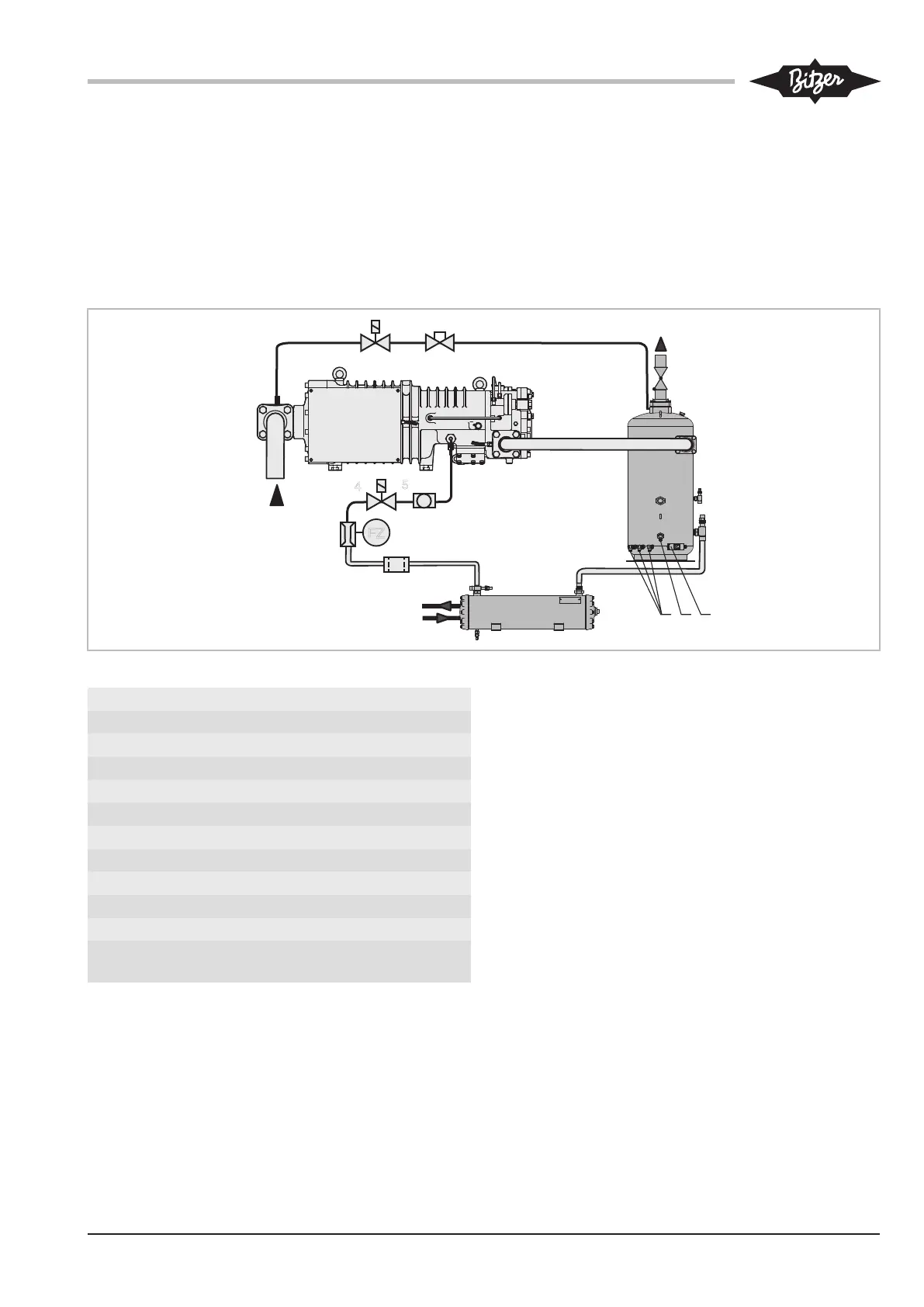
Install oil heater(s) in the oil separator and connect
them according to the schematic wiring diagram (see
also SH-100, SH-500). During long shut-off periods, the
oil heater prevents excessive refrigerant concentration
in the oil and therefore reduction of viscosity. It must be
on when the compressor is at standstill.
Insulate the oil separator:
• for operation at low ambient temperatures or
• with high temperatures on the high-pressure side
during standstill (e.g. heat pumps).
The oil level switch and the oil thermostat are sup-
plied separately and must be mounted on site.
Mounting position see figure 4, page 13.
9
11
7
8
6
FZ
10
2
3
4
5
1
12
∅ 6 mm (1/4")
Fig.4: Oil circuit (with a compressor)
1 Compressor
2 Oil filter
3 Oil flow switch
4 Oil solenoid valve
5 Sight glass
6 Oil separator
7 Oil level switch
8 Oil thermostat
9 Oil heater
10 Oil cooler (if required)
11 Check valve
12 Solenoid valve (standstill
bypass)