DB-300-924
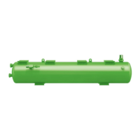
Connection positions
1 Refrigerant inlet
2 Refrigerant outlet
3 Oil outlet
4 Oil fill connection
5 OAHC maintenance
connection: Connection for pressure com-
pensation line
6 Oil thermostat connection
7 Connection for oil heating
7a Heater sleeve (for optional oil heater)
8 Connection for oil level switch
9 Connection for pressure relief valve
10 Oil outlet (secondary stage, with OAHC:
tertiary stage)
11 Maintenance flange for filter cartridges (fil-
ters of the secondary stage, with OAHC:
filters of the tertiary stage)
12 Fixing hole
13 Oil drain
Tab.5: Connection positions
Dimensions (if specified) may have tolerances accord-
ing to ENISO13920-B.
The legend applies to all BITZER oil separators and
contains connection positions that do not occur in every
oil separator series.