6. Short circuit the main output with 12AWG wire and check the display for CC setting by
varying the 5 kΩ variable resistor for current adjustment.
7. Switch off the power supply.
Remote Enable and Disable the Output
This remote output on/off control can be activated in any of the following modes: Normal,
Preset, Remote, and Set mode.
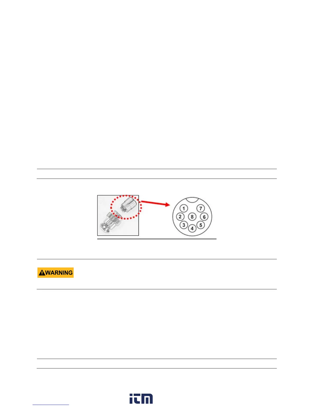
a. By default, Pin 5 is open and output is on.
b. Shorting Pin 5 to Pin 4 (ground) and output is off.
c. When the output is off, the CV and CC LEDs will flash. The current output voltage and
current setting will show on the panel meter.
d. You also can adjust the output by the voltage and current control knobs to the desired
value when the output is off.
Figure 21 - Analog Remote Control Connector
4.5 PC Interface Control
This PC Interface Mode connects the power supply to a PC via USB PORT. Application software
for wave form generator, external timed programs, data logging of output with I, V, W with
time span and the setting of miscellaneous parameters limits.
Note: using the 8 pin remote plug provided and connect with 22 AWG wires.
Do not use remote output on/off control when power supply is in Remote Sense
connection.
The power supply can be damaged due to the high current going through the thin remote
sense wires.
Note: The power supply does not need to have Remote control enabled to be controlled via the PC interface.
w ww . . co m
information@itm.com1.800.561.8187