19
1.8 7 7. 87 7. 2 2 6 9 BLACKBOX.COM
NEED HELP?
LEAVE THE TECH TO US
LIVE 24/7
TECHNICAL
SUPPORT
1.8 7 7.877. 2269
CHAPTER 5: INSTALL ATION
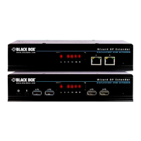
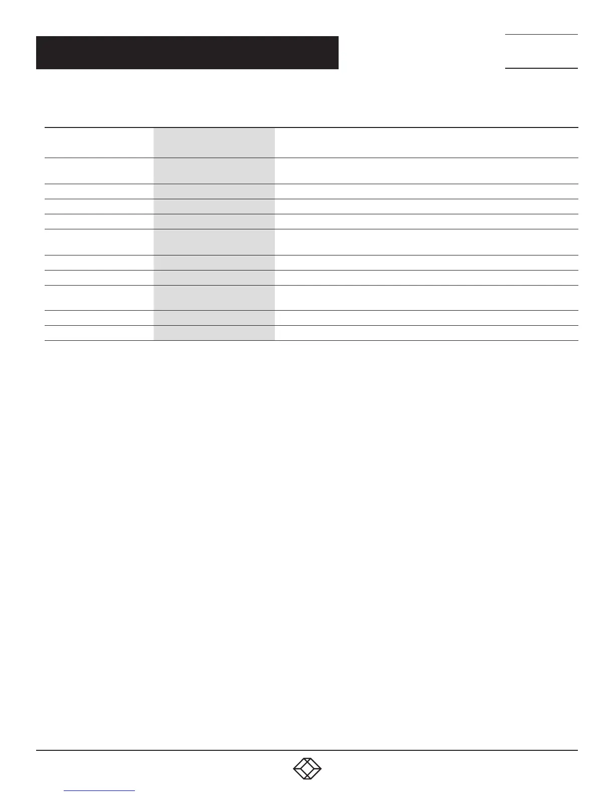
TABLE 5-1. EMERALD SE RECEIVER COMPONENTS
NUMBER IN FIGURES 5-1
THROUGH 5-4
COMPONENT DESCRIPTION
1 Power button
Disabled;
NOTE: The unit automatically powers on; it must be turned off at the power source.
2, 6 (4) USB Type A connectors Link to USB devices
3 (1) 3.5-mm connector Connects to microphone
4 (1) 3.5-mm connector Connects to speakers
5
(1) 2.5-mm barrel connector
for power
Links to 5-VDC external in-line power supply
7 (1) Link/Activity LED Lights green when there is activity on the link
8 (1) RJ-45 connector Links to 10-/100-/1000-Mbps network
9 (1) Link Speed LED
LED blinks green 1= 10 Mbps, 2 = 100 Mbps and 3= 1 Gbps in a 1.5 second interval.
No blinking means no valid link
10 (1) or (2) DVI output connectors Links to DVI output(s)
11 (1) DB9 connector* Links to RS-232 serial interface
*Single-head model only
 Loading...