OM6003.PUB Page 15 DATE PRINTED: 4/7/11
© Blaze King Industries Canada Ltd June 2006 Version 1.07SIT
The Contemporary by Blaze King Owners Installation and Operation Manual
Simpson Duravent vent systems use twist lock connections. The adaptor attached to the unit connects to the approved venting
system. Assemble the vent system using the desired combination of sections and fittings required for your particular installation.
While you are assembling the pipe bear in mind the best visual appearance. Seams should be aligned and
hidden as much as possible. Make sure you twist the mating section all the way to make a solid connection.
Note: As this system is a sealed system, a high temperature sealing compound must be used to seal the
metal to metal joint.
Apply a bead of high temperature sealant to both the 4” exhaust and 6-5/8” intake section of the
male pipe. The female section of the pipe/fitting has four indentations evenly spaced around the
pipe. These indentations are designed to slide over the male section of the pipe and locate into
the four entry slots of the male section of pipe. Twist the female section clockwise a quarter
turn to fully lock the sections together.
Vent Pipe Assembly Procedure
WARNING: A minimum clearance of 2” to combustibles must be maintained around the
vent pipe on horizontal pipe runs and 1” on vertical runs.
Installation Instructions
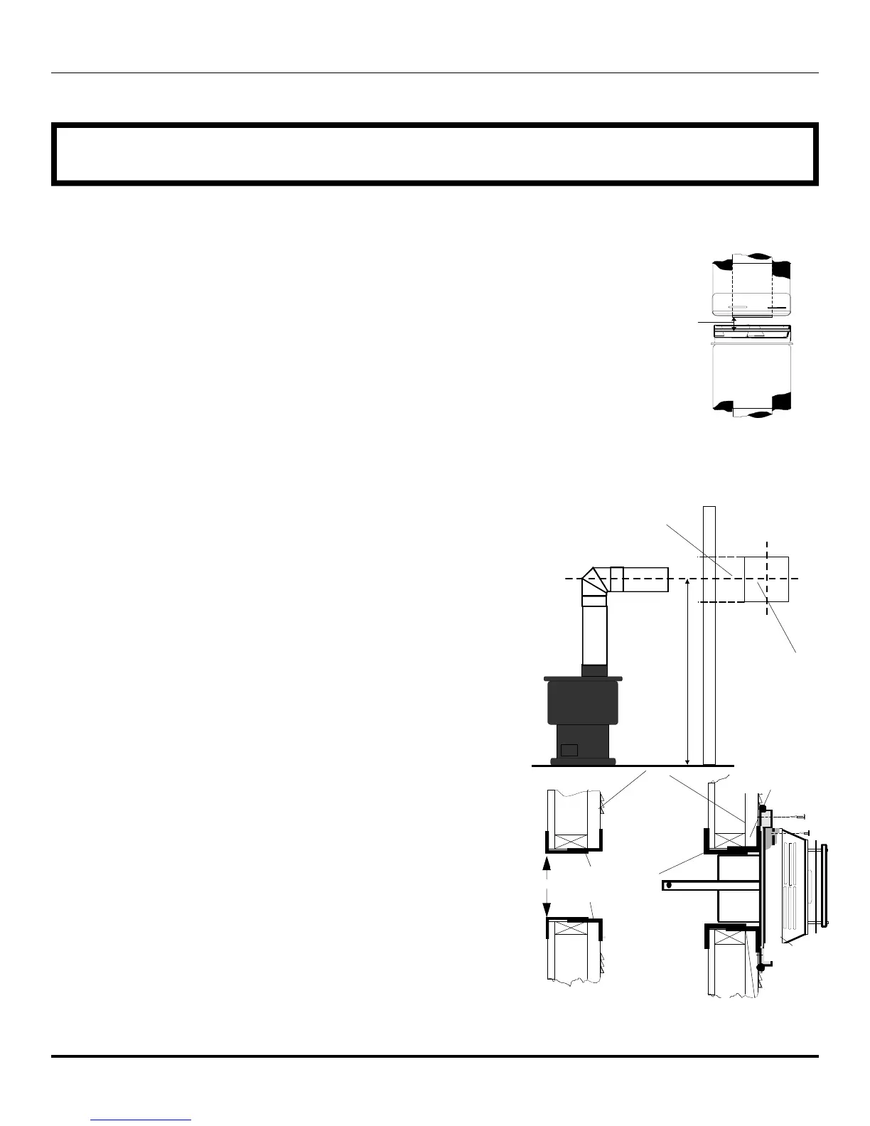
Attach the correct length of vertical section pipe and an elbow fitting to the
stove.
Mark the center line of the pipe facing the wall (allowing for a 1/4” rise per foot
of horizontal run). Example 10 ft of horizontal would require a rise of 2.5”.
NOTE: ALLOWING THE VENT PIPE TO SLOPE DOWN TOWARDS THE
VENT TERMINATION COULD CAUSE POOR COMBUSTION AND/OR
HIGH TEMPERTURES THAT MAY PRESENT A FIRE HAZARD.
Mark a 10” x 10” square around the center mark (inside dimensions).
Cut and frame the exterior wall to accept the wall penetration heat shield. Install
the penetration shield using wood screws. If the wall being penetrated is
constructed of non-combustible material a 7” hole sufficient for the vent pipe, is
acceptable.
Horizontal Wall Vent Terminations
The position of the horizontal vent termination must be positioned to meet all local building codes (see termination chart on page 17)
Caution: When installing the termination on to vinyl siding, a vinyl siding
kit or furring strips must be used. This prevents the termination from
being recessed into the siding.
Siding
Apply sealant
On four sides
Siding standoff
10”
Screws
C
L
C
L
Center of
hole
10” square hole
High
Temperature
Sealant
(Mil-Pac / RTV)
When the termination is to be attached to vinyl siding apply a bead of non-
hardening mastic around the outside edge to form a seal between the standoff
and the termination cap. Attach the termination cap to the exterior wall inserting
four wood screws through the holes in the corner of the vent termination.
Complete the installation by applying a bead of mastic around the outer edge of
the vinyl standoff. With the termination cap installed you can now connect the
completed vent assembly by sliding the unit back towards the wall and carefully
inserting the pipe into the terminal. Before the final connection is made slide on
the decorative wall thimble. Secure the termination cap by securing the
termination straps to the pipe as close to the exterior wall as possible using sheet
metal screws. Ensure that the straps are hidden by the wall thimble cover. Apply
decorative trim if required.
Wall penetration
heat shield