OM6003.PUB Page 27 DATE PRINTED: 4/7/11
© Blaze King Industries Canada Ltd June 2006 Version 1.07SIT
The Contemporary by Blaze King Owners Installation and Operation Manual
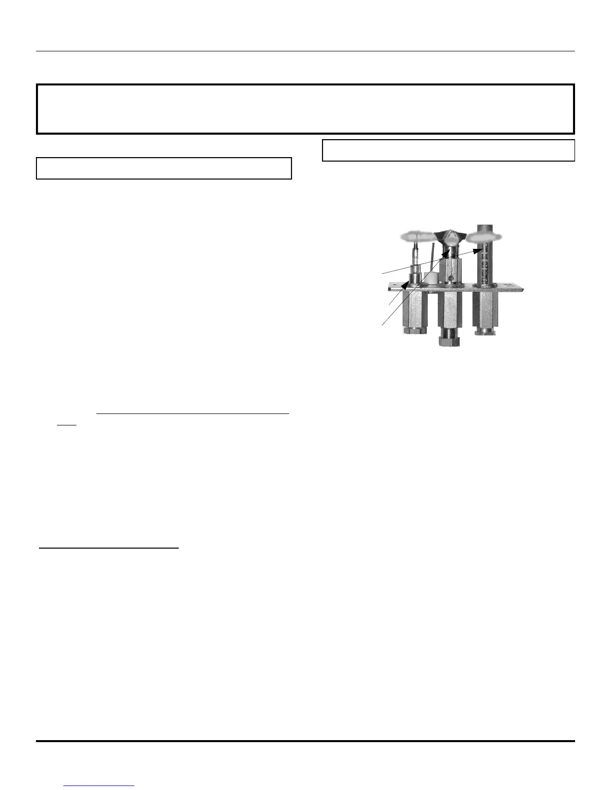
Thermopile
Thermocouple
Pilot for
Burner ignition
FREQUENCY OF SERVICE
Regularly:
Clean and remove any lint accumulations or debris from the
grills and combustion or convection air passage ways.
Keep the appliance area free from combustible materials, such
as paper, wood, clothing, gasoline, flammable solids, liquids
and vapors.
Visually check the height and color of the burner and pilot
flames.
Check for unusual noises or odors during operation of the
appliance.
Check the vent terminal for any damage, or obstruction by
plants or debris accumulation.
Once a Year:
Open the door assembly and clean the inside of the glass with a
soft, non-abrasive cloth and water or a suitable, mild, non-
abrasive cleaner.
Carefully remove the logs and gently brush off any loose carbon
deposits. This job is best done outside the house, wearing a
dust mask.The logs are very fragile, take care not to break
them. After cleaning, the logs must be replaced as per the
instructions in this manual.
Have a qualified service technician:
Completely inspect the appliance and the venting system.
Clean and remove any lint accumulations or debris in the
firebox, on the burners, on the pilot, at the primary air opening,
on the convection air blower and in any combustion and
convection air passage ways.
Check the safety system of the gas valve.
VENTING:
1.Check the venting system for any signs of
corrosion.
2.Remove the vent termination and check the inside
of the vent by shining a light down the pipe.
3.Inspect pipe seams and joints and ensure they are
still tight.
4.Check wall straps and all vent supports.
LOGS:
1.Check logs are correctly positioned (see installation
instructions).
2.Check there are no cracked logs.
3.Clean off any soot deposits using a soft brush.
NOTE: Incorrect log positioning may cause carbon
build up and discoloration. This may void the
warranty.
TECHNICAL INSTRUCTIONS
PILOT ASSEMBLY: The correct flame pattern
should have three strong blue flames. One flows
around the thermopile, one around the
thermocouple and one flows over the burner. See
page 31 for further pilot instructions
GAS VALVE REPLACEMENT:
1. Disconnect electricity to the appliance.
2. Shut off the gas to the appliance and disconnect the
gas line to the appliance.
3. If the appliance has a remote switch or thermostat,
disconnect the wires at the front of the valve.
4. Undo the four screws holding the valve plate to the
pedestal assembly.
5. Gently rotate the valve to gain access to the
millivolt wiring, pilot tube nut and burner supply tube
nut.
6. Carefully undo the pilot and burner supply tubes
and remove the valve.
7. Replacing the assembly is the reverse of the above
instructions.
Maintenance
CAUTION: NEVER CLEAN THE APPLIANCE WHEN IT IS HOT. ANY SAFETY SCREEN OR
GUARD REMOVED FOR SERVICING MUST BE REPLACED PRIOR TO OPERATING THE AP-
PLIANCE. DO NOT USE ANY SUBSTITUE MATERIALS.
REMOVING THE BURNER ORIFICE
1. Use a 1/2” wrench to loosen and remove the burner
orifice.
2. Change the orifice.
Pedestal Cover Removal
The pedestal cover must be carefully removed to access the gas
valve and connections. To remove the pedestal cover remove the 4
screws on the sides of the pedestal. Carefully lift the pedestal cover
slightly as you pull it forward off of the unit. The lifting is required so
that you do not scratch up the base. When the cover is removed you
should have easy access for connections and testing purposes.
When placing the pedestal cover back on the unit, use the same
caution. Carefully lift the cover and slide it over the pedestal, so that
you do not scratch the base. Then replace the 4 screws on the sides
of the pedestal.