PAGE 13
OM-8003 & 8004
Date Printed: Tuesday, February 08, 2005
Revision Date: 06-12-03
8003 INSERT ASSEMBLY INSTRUCTIONS
18. You may position the unit in your existing masonry or listed zero clearance fireplace at this time. If your hearth is lower than the
bottom of the fire place you must install the leveling bolts provided in the insert kit. Spin a lock nut onto each bolt, locate a threaded hole
underneath the front bottom portion of the fire box, one on the left, one on the right. Insert each bolt and adjust as needed. Be sure to
tighten the lock nut against the bottom of the fire box.
NOTE: If the bolts included in the kit are not long enough, simply obtain the appropriate length at your local hardware store or purchase a
Hearth Extension Kit from your Dealer
WARNING! INSERT IS FRONT HEAVY- USE CAUTION WHEN INSTALLING . TWO PEOPLE ARE
RECOMMENDED TO PERFORM THIS TASK
19. Connect the 1/2” flex gas supply line to the valve.
NOTE: The 8003 fire box comes with a wall thermostat. The leads should be hooked up to the terminals marked “TH” and “THTP”. (See
P. 21) Use 18 gauge or better wire.
20. Connect either single wall or flex pipe to the flue collar.
NOTE: If necessary to facilitate installation, the draft hood can be removed from the fire box, connected to the vent pipe, then re-installed
onto the stove.
21. Secure outer top to the main shroud with five screws. Position the back of top against the main shroud and line up the corresponding
holes. The screws will pass through the back of the shroud then into the top. (Fig. 35, p. 11)
22. Locate the two brackets that hold the decor above the viewing door. Note that there is a empty slot on each bracket, this is where the
bottom lip on the front of the outer top will engage.
23. Position the main shroud in front of the stove at a 45 deg. angle (top towards you). Engage the bottom “legs” of the shroud around the
outside of the lower left and right shrouds. (Fig. 36, p. 11)
24. Tilt the main shroud upward and engage the bottom inside lip of the outer top into the empty slots on the decor brackets. Square up
the main shroud to the fire box. (Fig. 37, p. 11)
25. Open the left shroud door. Note the holes now lined up to the right of the magnetic catch. Secure the main shroud to the upper
shroud bracket with one screw. Repeat with the right side.
26. Locate two access holes above the fan cord exits on both left and right sides of the main shroud. Pass a screw through the access
hole, through the second hole in the main shroud, and tighten to the lower shroud. Repeat with second screw.
27. Repeat with opposite side.
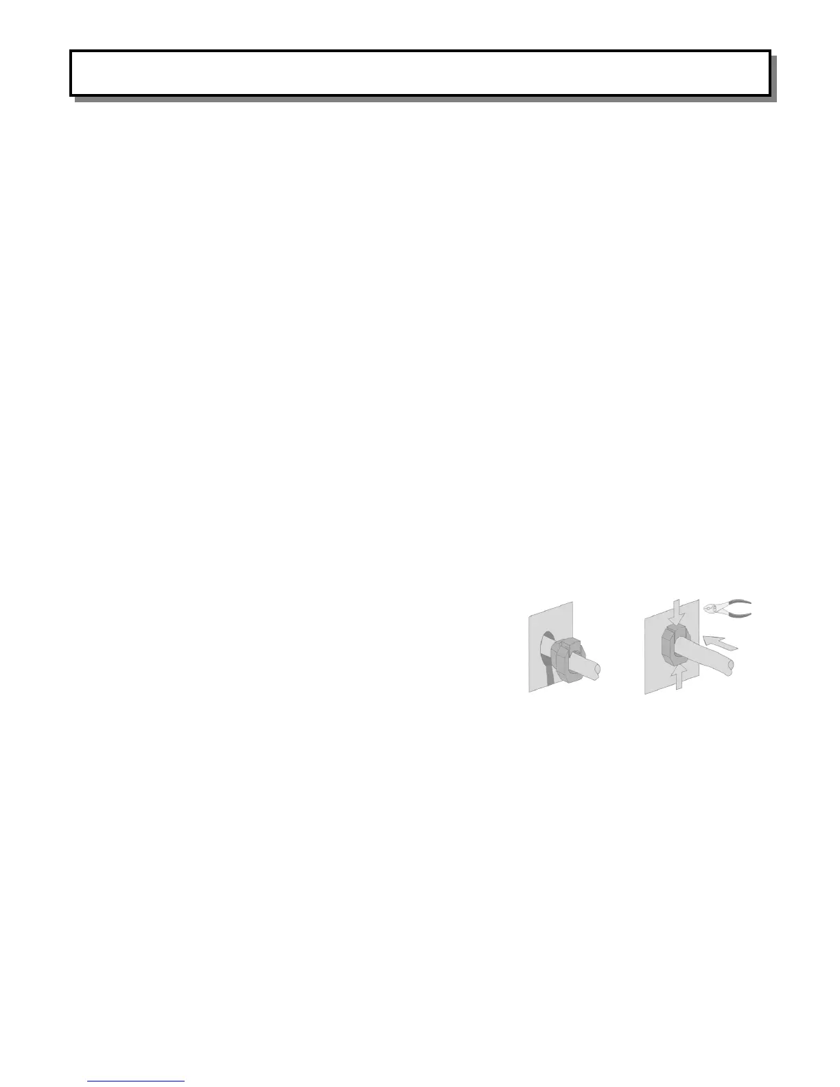
28. Take the fan cord and push it up into the exit hole on the side of the shroud. Wrap
the strain relief around the cord, compress the top and bottom with a pair of pliers,(see
illustration right) and push into the hole. Push insert flush against fire place.
INSERT TOP TRIM INTO THE RECESSED HOLE OF THE OUTER TOP
AT THIS TIME
AIR SHUTTER ROD INSTALLATION
Note: On all units manufactured from May 2003 and on the air shutter is installed at the factory.
To adjust open the viewing door and grasp small rod located in the back right of the firebox and with pliers lift up and/or pull down to adjust
the flame pattern as desired.
Note: If burner tray is removed:
MAKE SURE THAT THE SPRING IS IN PLACE ON THE MAIN BURNER ORIFICE, AND THAT THE MAIN BURNER
ORIFICE SEATS ITSELF INSIDE THE BURNER AIR SHUTTER.
STRAIN RELIEF INSTALLATION