PAGE 14
OM-8003 & 8004
Date Printed: Tuesday, February 08, 2005
Revision Date: 06-12-03
The gas line may be installed at this time. Make sure to follow all provincial and local codes. It is recommended
by Blaze King that gas connections be made by a licensed and qualified installer. The appliance can be
connected to the supply line with either rigid or approved flexible gas connection. Check with provincial and local
codes.
Attach a 1/2 inch close nipple to the control valve. At this point there must be a 1/2 inch N.P.T. plugged tee
accessible for a test gauge. The connection pipe connected to a 1/2 inch shut off valve, should be mounted to the
supply line.
PIPING DETAIL:
NOTE: DO NOT DAMAGE OR KINK THE FLEX CONNECTOR. CHECK FOR GAS LEAKS WITH SOAP AND
WATER SOLUTION.
1/2 INCH FLEX OR RIGID PIPING MAY BE USED TO CONNECT THE GAS SUPPLY TO THE UNIT
DEPENDING ON PROVINCIAL AND LOCAL CODES.
GAS SUPPLY PRESSURE:
NATURAL GAS............................7 inch w.c. recommended 5.5 / 1.37 min / 10.5 / 2.62 max
LP GAS.......................................11 inch w.c. recommended 11.0 / 2.74 min / 13.0 / 3.20 max
GAS CONNECTION
Robert Shaw and Honeywell valves have built in line and manifold pressure taps built in for easy access.
1/2” Gas Shut Off Valve Open Position
Supply Line
1/2” Flex Connector Or Rigid Pipe
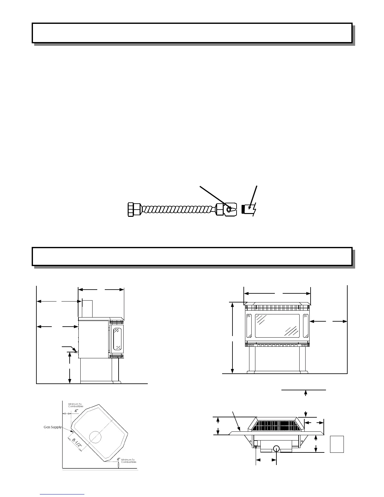
8003 & 8004 CLEARANCE DIAGRAMS
8004 FREE STANDING
8003 INSERT
8004 FREE STANDING
20”
6”
Min. To
5-1/4”
Min. To
18”
Gas Supply
8004 FREE STANDING
25”
11”
Min. To
Combustables
30”
12”
With
45 Deg.
9 1/2” Str. Up
10”
13
C
11”
Min. To
Combustables
Shroud Can Not Touch Combustables
If Unit Is Less Than 6” Above Floor Level
R1.1 Protection Is Required At Least 18”
InFront Of Unit. (3/8” Millboard Is Sufficient)