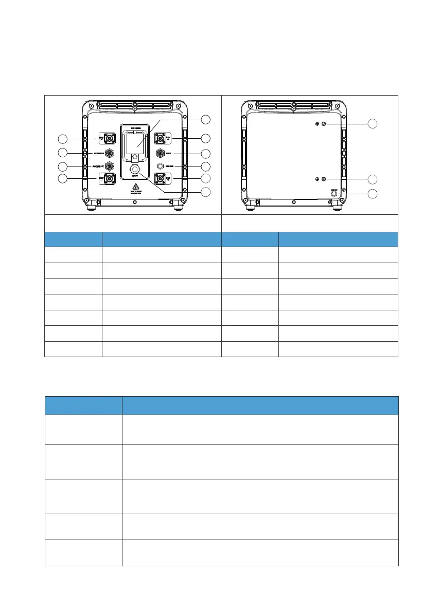
4.3.2 Wiring Interface Instructions
Interface
To Pcs
(Inverter signal port)
For communication between inverter and battery packs. Only the top
B500 needs to be connected to the LINK PORT 2 of the inverter.
Connect to the BAT+ terminal of another B500 or the inverter.
Connect to the BAT- terminal of another B500 or the inverter.
For communication between battery packs. Connect to the PACK LINK
OUT port of the upper battery when multiple B500s are stacked (except
for the top B500).
For communication between battery packs. Connect to the
PACK LINK IN port of the lower battery when multiple B500s are stacked
(except for the bottom B500).
PACK LINK IN
PACK LINK OUT
BAT+ terminal
BAT- terminal
Description
Table 4-4
1
2
3
4
5
6
7
8
9
10
11
12
13
Table 4-3
Left
No.
1
2
3
4
5
6
7
No.
8
9
10
11
12
13
BAT- terminal 1
Pack link-in
Pack link-out
BAT- terminal 2
Main switch
BAT+ terminal 1
To Pcs(Inverter signal port)
Bleed valve 1
BAT+ terminal 2
Power button
Grounding port 1
Grounding port 2
Bleed valve 2
Name Name
Right
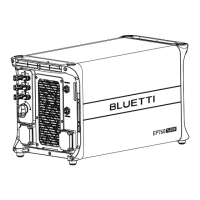
4.3 Interfaces
4.3.1 Interface Description
JUST POWER ON30