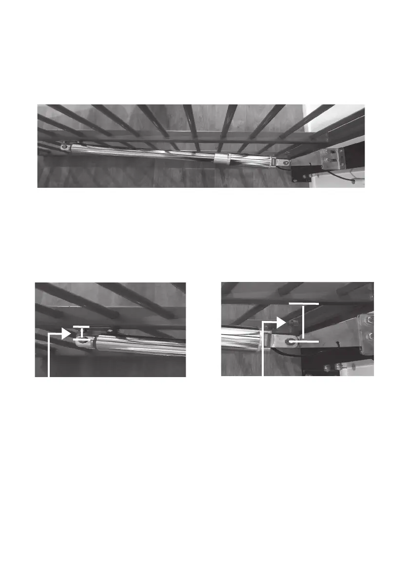
Pull-to-Open Setup
Checking the minimum clearance required between the actuator arm and gate
if the J & K measurements listed on page 16 are unattainable
Image above shows the gate in the open position with the arm retracted and
using the standard gate bracket and post brackets supplied in the kit.
Minimum clearances required between the gate and actuator arm are shown
below with the gate in the open position and arm fully retracted - this is to
prevent the gate opener from running parallel with the gate.
1. Minimum measurement required
between centre pin and gate
2. Minimum measurement required
between centre back pin and gate
Using standard gate bracket = 35mm
Using round gate bracket = 47mm
Using standard gate bracket = 110mm
Using round gate bracket = 122mm
Ensure there is sufcient angle so that the gate never runs parallel with the
actuator arm in either the closed or open positions.
It is important that in both the full open and full close positions, the arms must
not be parallel to the gate. A parallel arm will not result in a turning movement
to the gate causing potential damage to both gate and actuator arm.