EasyManuals Logo

BobsCNC QUANTUM MAX User Manual

Default Icon
176 pages
To Next Page IconTo Next Page
To Previous Page IconTo Previous Page
Page #166 background imageLoading...
Page #166 background image
165
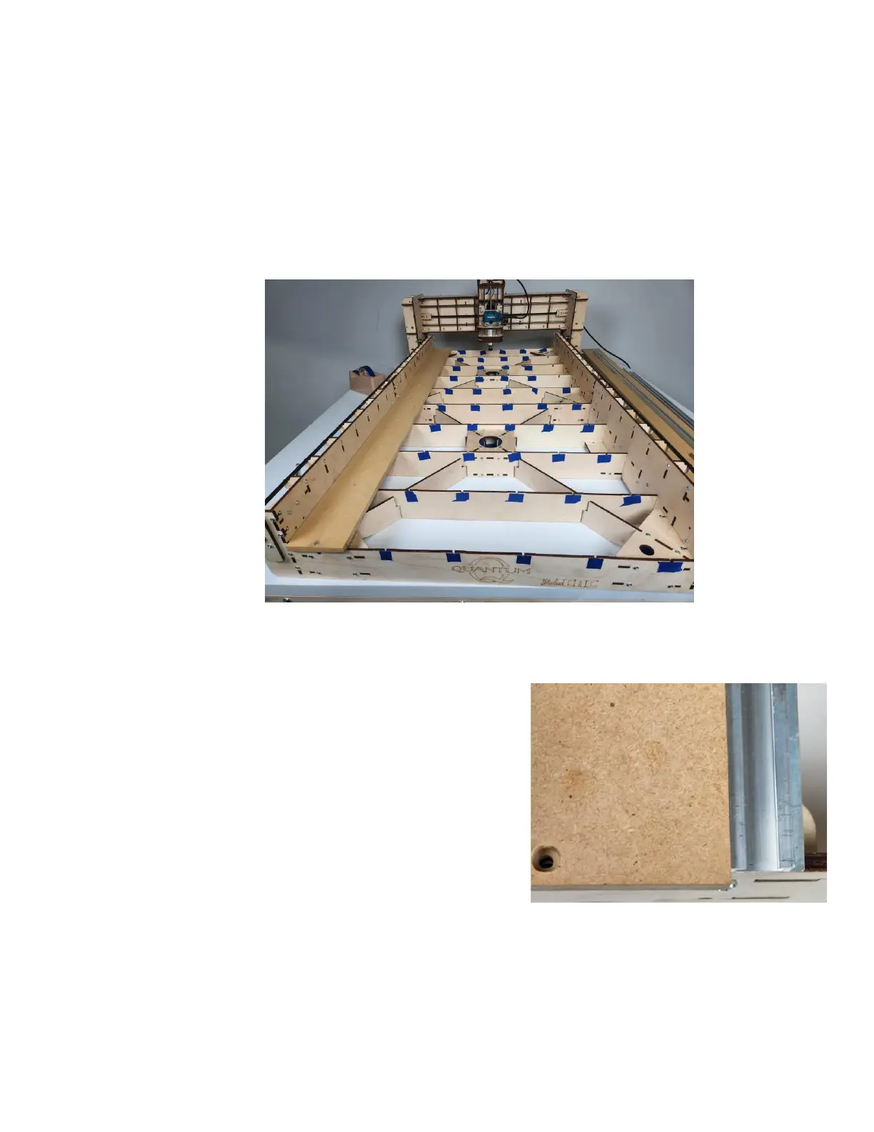
Step 2 Lay the first MDF Section against the left side of the
X Frame Assembly as shown. Make sure the
countersunk openings are facing up. Align the holes
with the installed M4 nuts beneath. Install the
Machine Screws to hold each Section in place but
do not tighten them at this time.
Step 3 Lift the MDF Section and set
the flange of the Aluminum
T-Slot so that the MDF
covers it completely. Align
the front and back end of the
Aluminum T-Slot flush with
the front and back end
panels as shown.

Questions and Answers:

Question and Answer IconNeed help?

Do you have a question about the BobsCNC QUANTUM MAX and is the answer not in the manual?

BobsCNC QUANTUM MAX Specifications

General IconGeneral
BrandBobsCNC
ModelQUANTUM MAX
CategoryControl Systems
LanguageEnglish

Related product manuals