EasyManuals Logo

BobsCNC QUANTUM MAX User Manual

Default Icon
176 pages
To Next Page IconTo Next Page
To Previous Page IconTo Previous Page
Page #95 background imageLoading...
Page #95 background image
94
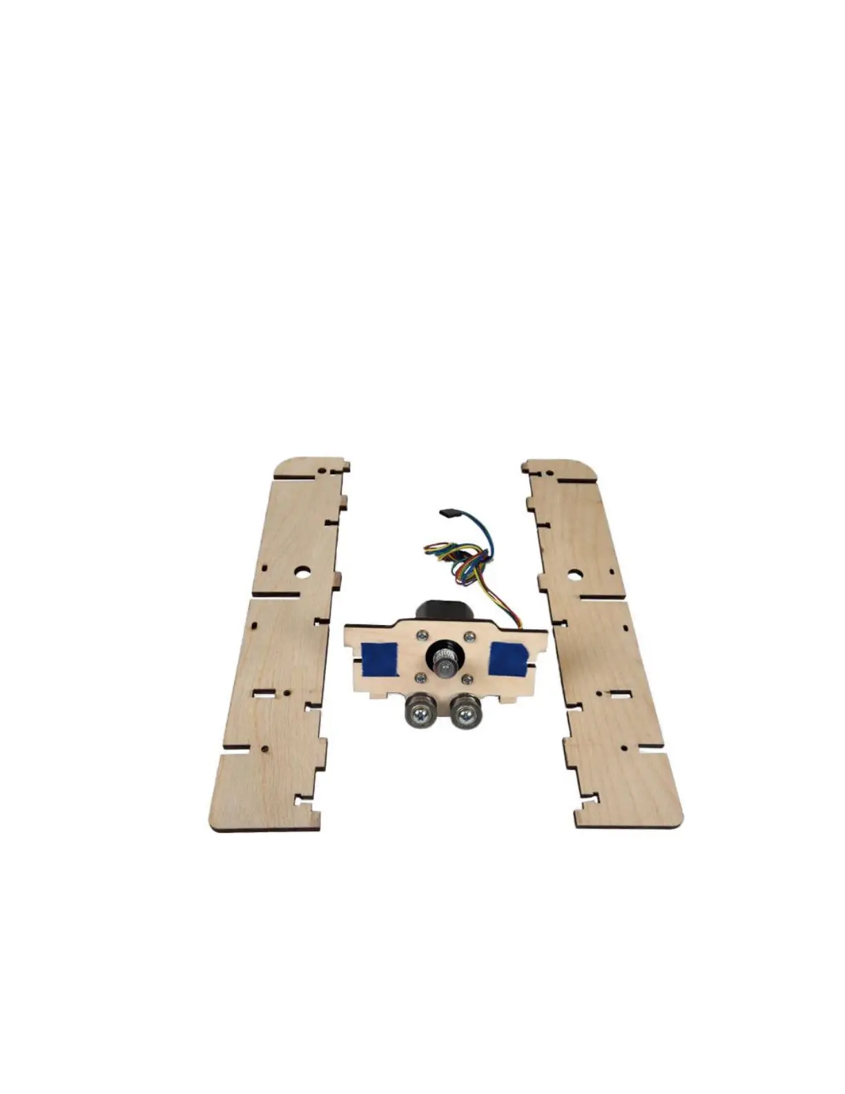
Step 1a Layout two Gantry Side Supports (QG2) and a
completed Stepper Motor Mount Assembly.
Be sure that with the Idler Bearings resting on
the table (as shown below), ensure the
Stepper Motor Wires are oriented in the
correct direction as shown in the photo below.
Install two M4 Nuts and use small pieces of
tape to cover the T-slots on the bottom of the
Stepper Motor Mount to retain the Nuts.

Questions and Answers:

Question and Answer IconNeed help?

Do you have a question about the BobsCNC QUANTUM MAX and is the answer not in the manual?

BobsCNC QUANTUM MAX Specifications

General IconGeneral
BrandBobsCNC
ModelQUANTUM MAX
CategoryControl Systems
LanguageEnglish

Related product manuals