11.0 Logic Board
The printed circuit boards used in this product have been manufactured using surface mount technology. These printed
circuit boards cannot be effectively repaired in the field and should be returned to the manufacturer if repair is required.
Warning: ALL SERVICE SHOULD BE DONE WITH POWER OFF AND THE AC CORD UNPLUGGED
FROM THE PRINTER.
11.1.1 Logic Board (Removal)
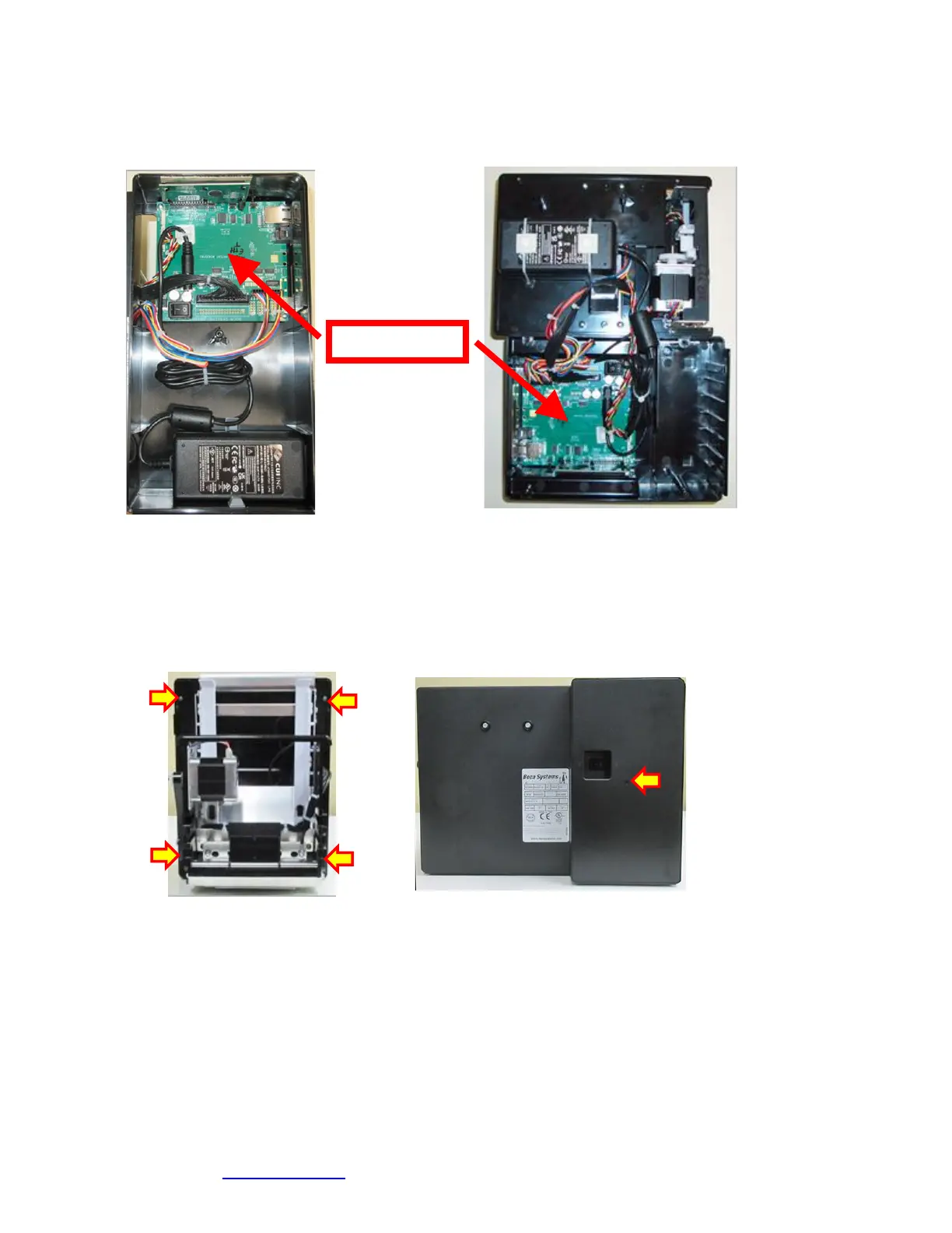
1. Gain access to the logic board. This is normally done by removing the electronics cover or rear access panel.
a. Lemur & Lemur-K - Remove 4 Philip head screws.
b. Lemur-S (plastic cabinet) – Remove 1 Philip head screw.
Lemur Lemur-S
2. Denote where all the cables are plugged into the logic board.
3. Unplug connectors connected to the main logic board.
4. Remove the four phlip head screws that secure the logic board onto the cabinet.
5. Lift board and remove.
11.1.2 Logic Board (Installation)
1. Installed the logic board into the printer.
2. Install the four Phlip head screws that hold the logic board onto the cabinet and tighten.
3. Attach connectors going to the main logic board.
4. Install the electronics cover or rear access panel.
Click here to return to > Table of Contents