26
V - Wiring
The wiring diers according to the board to be installed.
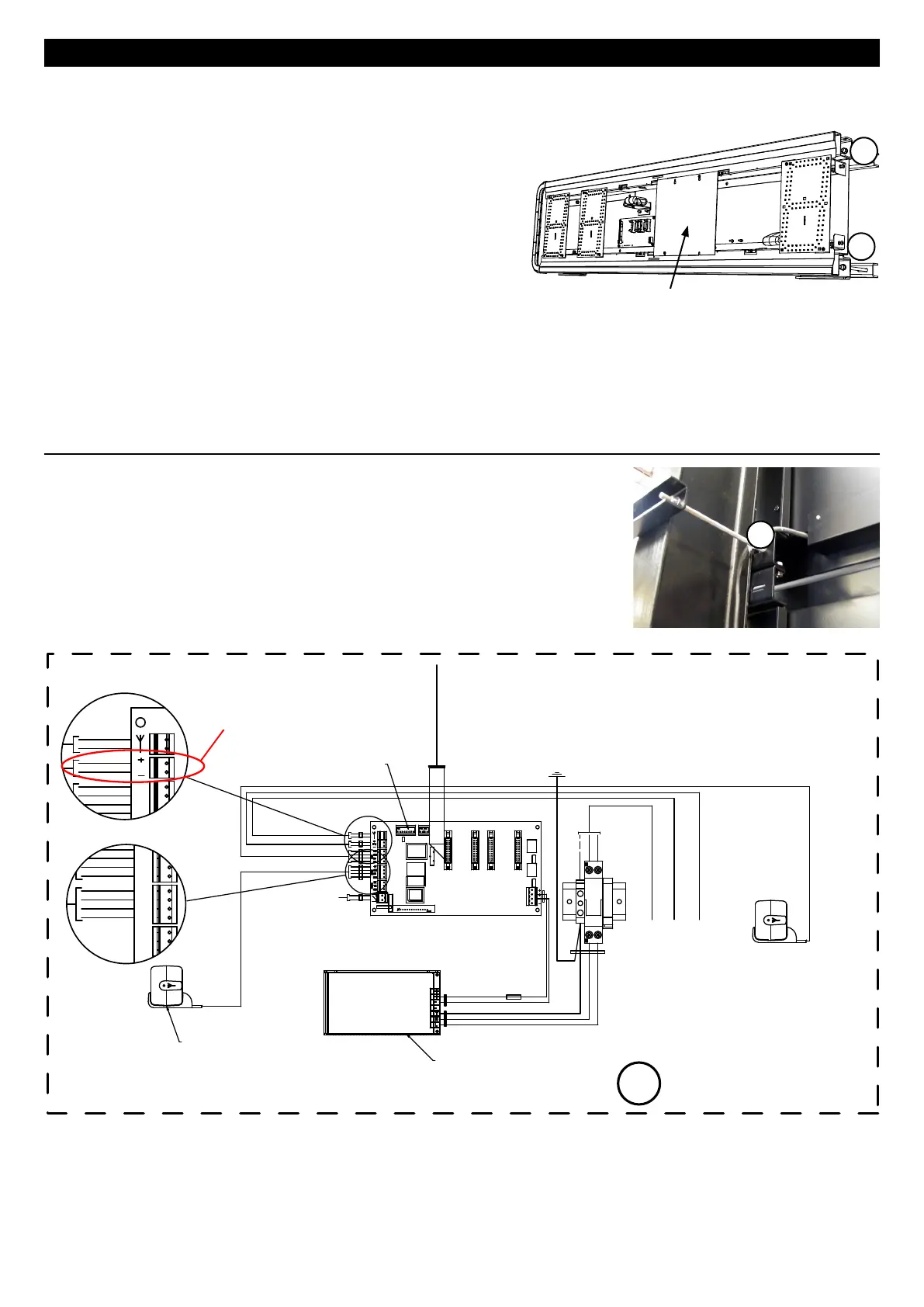
• To open a panel, unscrew the 4 screws (BT2045) or the 2 screws (BT2025) (A) on one of the sides
and remove the side. Pull the glass pane out sideways.
Caution : to avoid scratching the glass pane while
pulling it out, carefully avoid any contact between
the pane and the screws or LEDs.
Note : the glass pane of a BT2045 cannot be pulled
out completely.
• To access the electronic board or the power supply unit,
you must unscrew the 2 covers on the front.
• The scoreboards can be powered by 230V or 110v.
The procedure required to adapt the power supplies
to the input voltage is described on page 24.
A/ BT 2025 SCORE & CLUB / BT 2045 SCORE & CLUB
• Connect the mains power supply on the mains unit of the master
panel (A).
• If they exist, plug in the DCF antenna or the GPS antenna (see page
23).
• (B) The power supply cables must come out on the left side (rear
view) along the post.
B
+V
GND
RT-
RT+
+V
GND
RT-
RT+
GPS MDM
T °C
ON
2187
ON
215 64
ON
21 3
RX
TX
GND
RS232
L
N
T
+
+
-
-
1 42 3
Mains power supply
Temperature sensor wiring
GPS antenna wiring
DCF antenna wiring
Power supply
868 MHz modem
+V
GND
RT-
RT+
MDM
Yellow
Green
Brown
White
T °C
Brown
White
Dips
To modules
Temperature probe
A
A
A
Cover
 Loading...