29
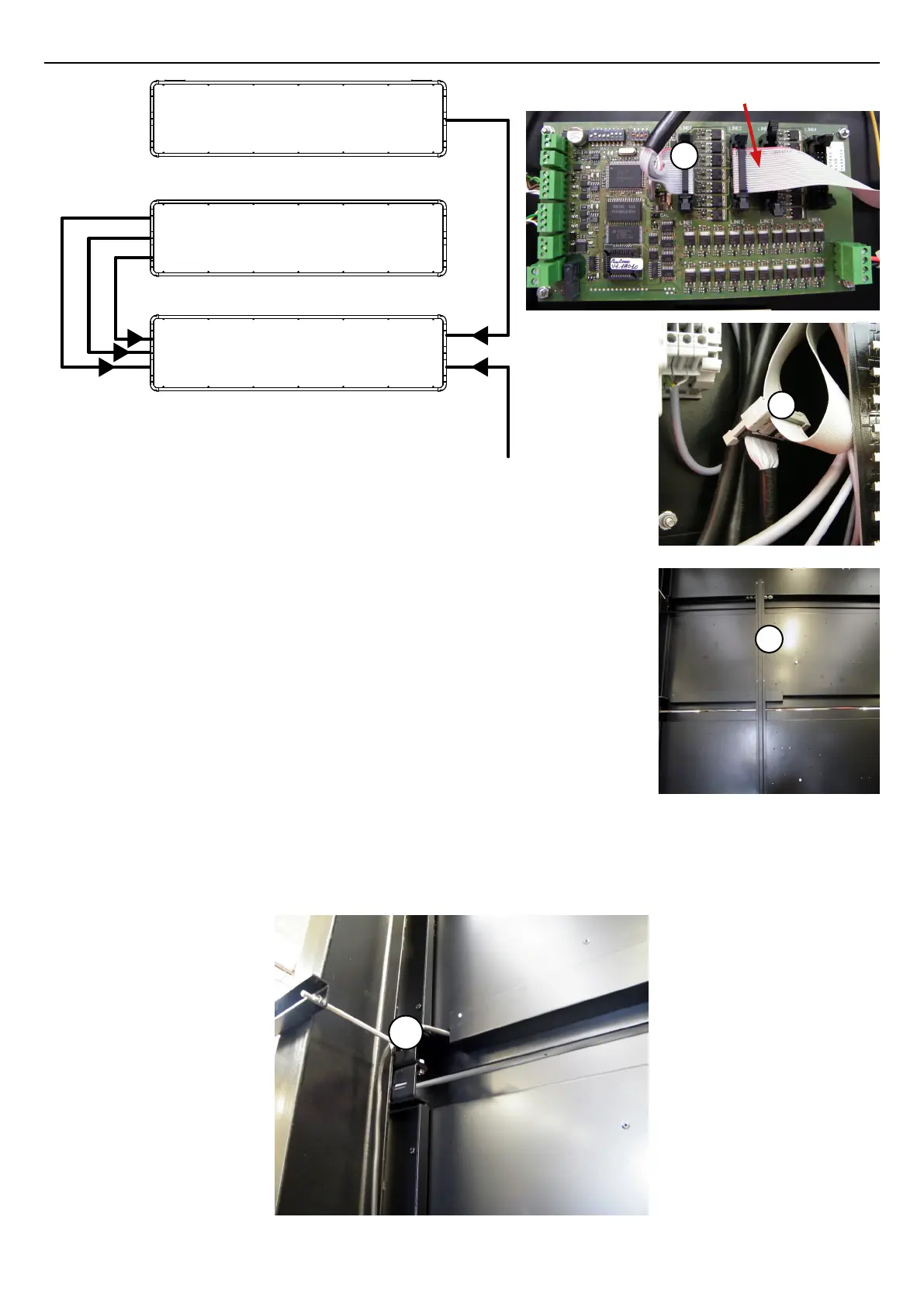
D/ BT 2045 ALPHA
• (A) Connect the at cable from the timer panel to connector 1 on the
electronic board of the master panel.
• (B) Connect the at cable from the HOME Alpha score panel to the
master panel connector on the at cable for control of the GUEST score
modules.
• (C) Connect the control wires (GND green, RT- brown and RT+ white)
of the alphanumeric readout from the HOME Alpha score panel to the
terminal strip on the master panel.
• (D) Connect the power supply from the HOME Alpha score panel to the
terminal strip on the master panel.
• (E) Connect the mains power supply on the mains unit of the master
panel.
• If it is used, plug in the DCF antenna (see page 23).
• (F) The control cables must run inside the cable duct.
• (G) The power supply cables must come out on the left side (rear view) along the post.
B
A
Flat cable for GUEST
score control
Timer panel
HOME ALPHA score panel
Master panel
HOME Alpha module power supply
HOME Alpha control
HOME score module control
Module control and power supply
Power supply
F
G
 Loading...