S2000M MAINTENANCE GUIDE
15
2 Maintenance
2.1 Preparation the product
2.1.1 General information
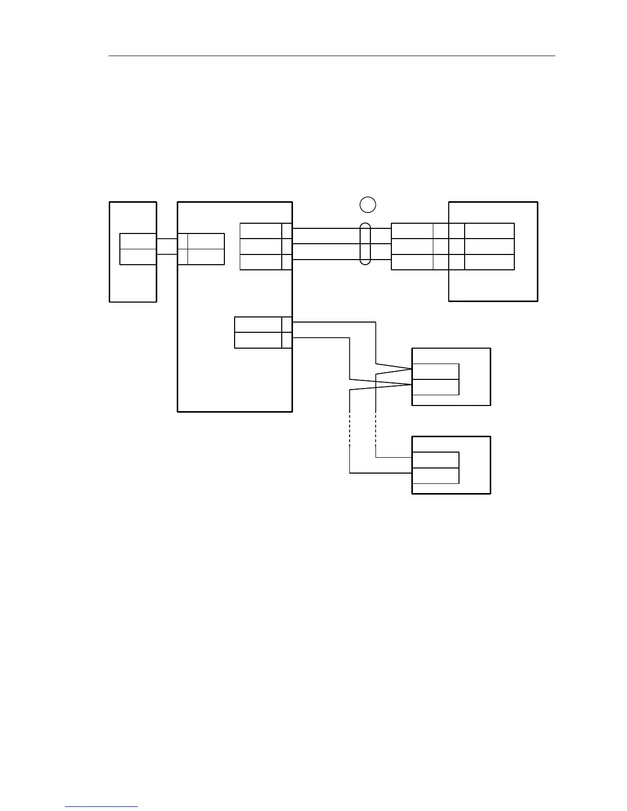
Console uses RS-485 interface to connect fire-alarm system devices, RS-232 interface to
connect printer with consequence interface or personal computer, and contacts to connect
reserved DC power supply. For additional price printer and computer connection cables are
supplied. Typical connection circuit is shown on the Figure 1.
S2000М
XT1.1
Device
Power
supply
0V
U
XT1.2
3A
4B
0V 1
+U 2
Printer
COM
(DB25F)
GND
DTR
RxD
RS485A
RS485B
XT1.3
5TxD
6DTR
GND 7
brown
white
green
1
7
3
20
GND
RxD
DTR
7
3
20
Plug
DB25M
Device
RS485A
RS485B
С2000М – fire check and control console;
Device – one of the "Signal-20", " Signal-20P", "S2000-4", "S2000-KDL", "S2000-SP1", "S2000-К",
"S2000-КS", "S2000-BI", "S2000-IТ" or "S2000-2";
Printer – printing device with serial interface RS-232
(e.g, Epson LX-300 or LX-300+);
1 – printer connection cable;
Power supply – DC power supply from 10,2 to 28,4 V current supply no more than 150 мА.
Figure 1 Typical maintenance connection ‘S2000M’ console circuit
Attention! On the console board there is 5-pin auxiliary slot. It is prohibited to set pin
tampers or shortly connect the pins if console power is on.
At mounting fire-alarm signal system console and other devices has to be customized.
First of all, each device connected to console through ‘RS-485’ interface has to have unique
network address. Panel cannot poll devices if they have identical addresses. Address values from
1 to 127 are valid. See item 2.1.2 for details. More over, each device has set of configuration
parameters, which determine its work algorithm. Changing values of the parameters, devices
work algorithms can be changed according system requirements (item 2.1.3). Addresses for