FIRE AND ALARM CONSOLE
22
To realize the second reservation mode it is necessary to assign the console with the
address and set the RS-232 operating mode to the value “S2000 & PC”. Refer to the section
2.2.4.8 for more details.
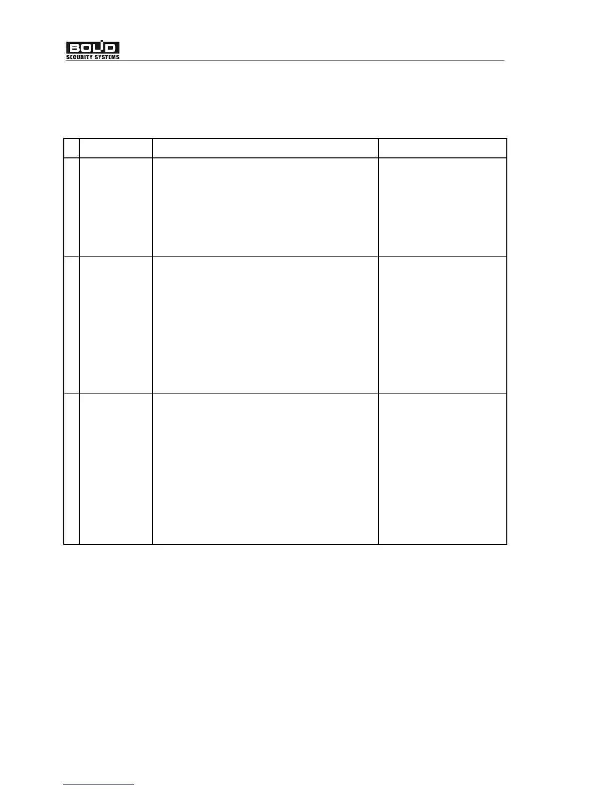
The following Table 9 summarizes the essentials of all available backup techniques.
Table 9 Available backup techniques
№ Technique Technique description Configuration method
1
Disconnected
console
and relay
switching
The monitoring and controlling are carried out
from the computer. The console is active but
disconnected from the system. When the PC
has stopping poll the devices for given time the
console has automatically connected to the
devices with the help of “S2000M-SP1” relay
unit.
In accordance with the
“S2000M-SP1” relay unit
maintenance guide
2
Passive
console
and automatic
switching
The monitoring and controlling are carried out
from the computer. The console is directly
connected to the computer via RS-232
interface, with the the devices being connected
to the console through RS-485 interface. The
console doesn’t control devices, doesn’t show
their states and is unresponsive to key
pressions. When the PC has stopping poll the
devices for given time the console has
automatically switches to the active mode.
In accordance with the
2.2.4.8 section ot this
maintenance guide set
RS-232 operating mode to
the “S2000 / PC” value
and give the switching
delay
3
Active console
The console is directly connected to the
computer via RS-232 interface, with the the
devices being connected to the console through
RS-485 interface. The console monitors all the
devices and gets their states, with the computer
polling the concole (or consoles) and getting
the device operative information. Both the
console and the computer can control the relay
outputs and indication units. If the computer
fails the console will retain to execute the
controlling functions.
In accordance with the
2.2.4.8 section ot this
maintenance guide set
RS-232 operating mode to
the “S2000 & PC” value
and give the own console
address
Note that the techniques 1 and 2 are obsolete but technique 3 is recommended.
Figure 5, Figure 6 and Figure 7 demonstrates the connection diagrams.
Figure 5 shows the simplest way to connect the console to the computer. The defect of
this way is the galvanic coupling between the PC and system devices through the RS-232
interface. This galvanic coupling result to the devices or RS-485 interface and the PC interfere to
each other.
To isolate the PC from intrusion and fire alarm panelss the RS-485 interface repeaters
with galvanic isolation, e.g, “S2000-PI”, can be used. The connecting diagram providing
galvanic isolation RS-485 line by ‘S2000-PI’ device is shown on the Figure 6. Note that to
provide isolation the console and interface repeater should be powered by separate source
without ‘0 V’ circuit of this source coupling with the ‘0 V’ devices circuit.