3.4 Control inputs and outputs
NOTE
Switch off power supply before connecting or disconnecting the control inputs and outputs. Other-
wise, components may be damaged.
• The unit may only be connected with the power supply switched off.
• Verify safe isolation from power supply.
3.4.1 Control terminals
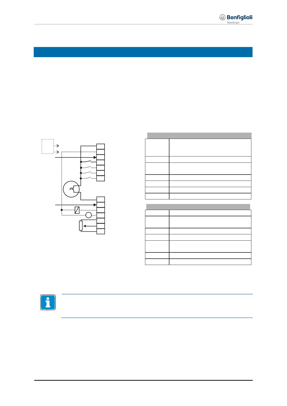
The wiring diagram describes the default assignment of control terminals and functions. According to
the requirements of the application, other functions can be assigned to the control terminals.
Without encoder:
Voltage output +20 V or input for
external power supply DC 24 V
GND 20 V/ GND 24 V (ext.)
Digital input STOA (1st shut-down
path of STO safety function)
Start of clockwise operation
Start of anticlockwise operation
Digital Input STOB (2nd shut-down
path of STO safety function)
Analog signal of actual frequency
Supply voltage +10 V for reference
value potentiometer
Reference speed 0 ...+10 V
With encoder:
A reference pulse sensor can be evaluated with the digital input S6IND of the basic unit.
In use of a speed sensor is required an additional extension module EM-xx.
Regarding the terminal assignment see the operating instruction of the concerned
S7IND
S1OUT
MFO1A
+10 V/4 mA
MFI1A
GND 10 V
1
2
3
4
5
6
7
X210A
+20 V/180 mA
GND 20 V
S1IND
S2IND
S3IND
S4IND
S5IND
S6IND
X210B
1
2
3
4
5
6
7
M
V
+
-
+
-
STOA
STOB
24 V
ext.
11/13
ACU
Spindle Applications 23

 Loading...

