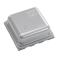
Bosch Sensortec"| BST-BMP581-DS004-02 31 | 74
Modifications reserved | Data subject to change
without notice Document number: BST-BMP581-DS004-02
5 Digital Interface
The device provides one serial interface to the host. It acts as a slave to the host The serial interface is configurable to
the interface protocols SPI, I3C and I2C.
5.1 Protocol Selection
The protocol is automatically selected based on the behavior of the signal on the chip select pin CSB after power-up.
After soft reset or power-up, the primary interface of the device is in I²C/I3C mode. If the CSB is connected to VDDIO
during power-up and not changed, the primary interface works in I²C or I3C mode.
For using I²C and I3C, it is recommended to hard-wire the CSB line to VDDIO. Since power-on-reset is only executed
when both VDD and VDDIO are stable, there is no risk of an incorrect protocol detection due to the power-up sequence.
Once the CSB input pin is falling low, the I²C/I3C mode is disabled. The HIF switches over to SPI mode if there are at
least 16 full serial clock (SCK) edges during the CSB low phase, and CSB has risen again. Hence, it is recommended
to perform a single read via SPI of a registers (e.g. to CHIP_ID) before the actual SPI communication with the device.
Note: the content of the retrieved data will be invalid.
The switch from I²C to I3C follows the MIPI I3C specification. Upon power up, the chip stays in I²C mode and once the
dedicated Broadcast I3C Address (7’h7E) is seen on the bus, the chip will disable its I2C feature and the interface stays
in the I3C mode until a soft reset or the next power-up occurs.
The possibles switches among the modes on the digital interface are summarized in Table 15.
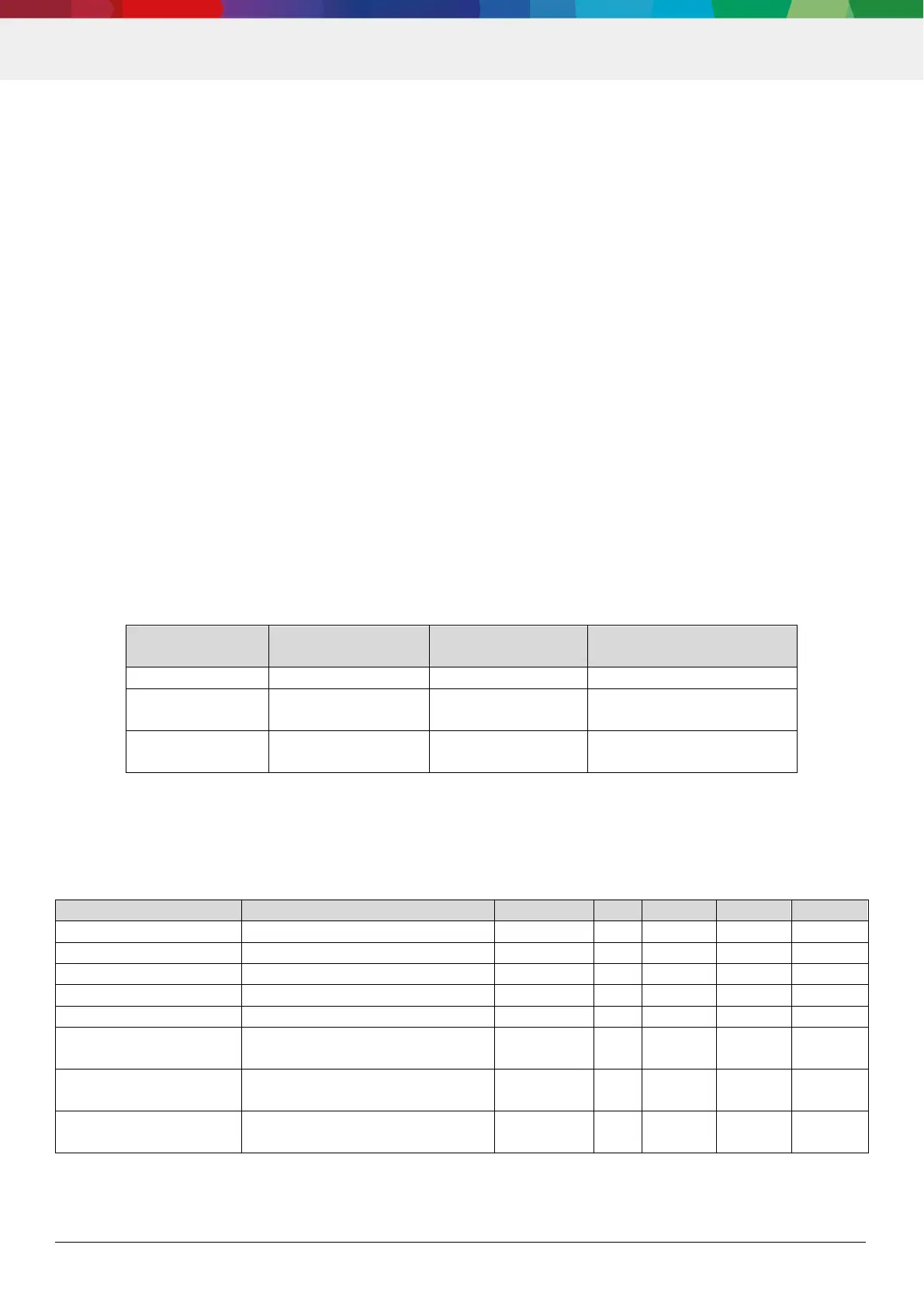
Table 16: Possible switches between interface modes
reset
reset
reset
5.2 Interface timing
The general interface parameters are given in the table below.
Table 17: General interface parameters
@VDDIO=1.2V/1.8V/3.3V+/-10%
@VDDIO=1.2V/1.8V/3.3V+/-10%
@VDDIO=1.2V/1.8V/3.3V+/-10%
@VDDIO=1.2V/1.8V/3.3V+/-10%
@VDDIO=1.2V/1.8V/3.3V+/-10%
Current (no pull-R)
Current (no pull-R)
CSB pin
I2C mode, relevant for interface
mode selection