Bosch Sensortec"| BST-BMP581-DS004-02 32 | 74
Modifications reserved | Data subject to change
without notice Document number: BST-BMP581-DS004-02
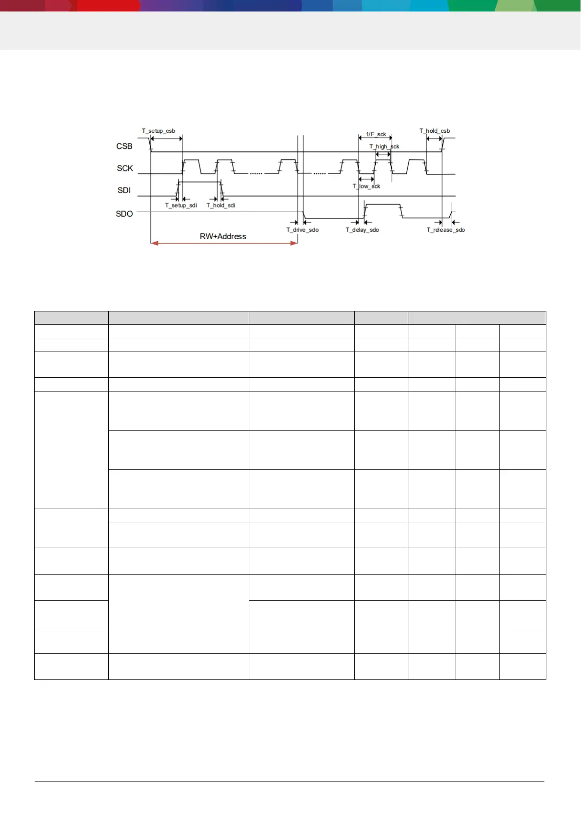
5.2.1 Interface timing
The timing diagram for SPI is given in Figure 7 and is valid for all SPI configurations. The corresponding values are
given in
Figure 7: SPI timing diagram (SPI4, Mode 0
Table 18: SPI timings
time
turnaround
time
90%/10% Master rise/fall time
= [2, 10]ns @ Cbus = 40pF,
drive_strength = 7
90%/10% Master rise/fall time
= [2, 10]ns @ Cbus = 80pF,
drive_strength = 7
90%/10% Master rise/fall time
= [2, 10]ns @ Cbus = 80pF,
time (90%/
10%)
frequency
High Time
Idle time after
write access
Idle time after
read access