Bosch Sensortec"| BST-BMP581-DS004-02 46 | 74
Modifications reserved | Data subject to change
without notice Document number: BST-BMP581-DS004-02
6 Pin out and connection diagrams
6.1 Pin Out
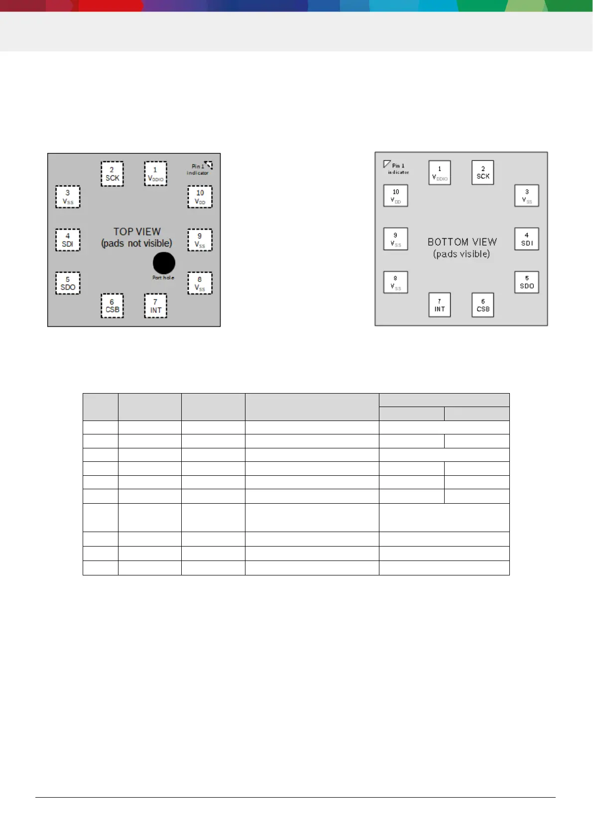
Figure 23 shows the pin-out of the device from top and bottom view, respectively. Table 25 shows the related pin
descriptions.
Figure 18: Pin out top and bottom view
Table 28: Pin description
DDIO
a
DD
a. GND connection is allowed, as long as the IRQ pin is not activated
6.2 Connection Diagrams
The sensor (including the ASIC) should be used in one of the following four configurations on application level. In all
connection scenarios:
all VSS pins must be connected to GND.
if the INT pin is not used, it is recommended to be connect it to GND, rather than leaving it floating. In the case of
GND connection, the interrupt pin must be disabled by keeping INT_CONFIG.int_en disabled. . If the INT pin must
be unconnected in the application, it is recommended to use the following settings for INT_CONFIG:
INT_CONFIG.int_en = 1
INT_CONFIG.int_od = 0
INT_CONFIG.pad_int_drv =