Bosch Sensortec"| BST-BMP581-DS004-02 47 | 74
Modifications reserved | Data subject to change
without notice Document number: BST-BMP581-DS004-02
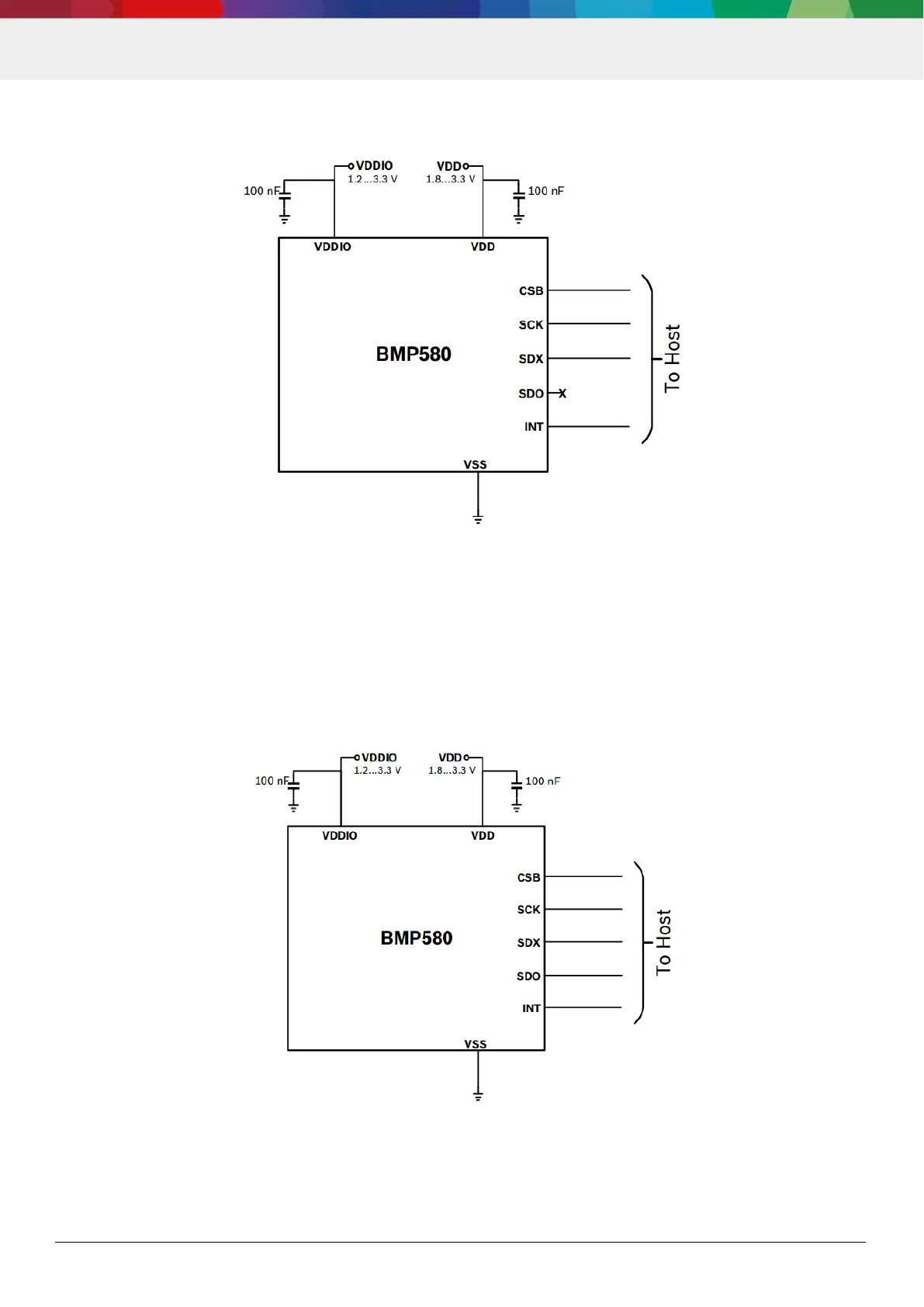
6.2.1 SPI 3-wire
Figure 19: SPI 3-wire connection diagram
The SDO pin must be left floating. The reason is, that the device starts in SPI4 mode after power-up, and drives SDO
until the switch to SPI3 is commanded.
The SDI pin must be driven to either low or high voltage when no communication takes place. Otherwise, a floating SDI
may create excessive power consumption (and on the longterm potentially also damage to the device), as the input pad
is not disabled.
6.2.2 SPI 4-wire
Figure 20: SPI 4-wire connection diagram