Bosch Sensortec"| BST-BMP581-DS004-02 45 | 74
Modifications reserved | Data subject to change
without notice Document number: BST-BMP581-DS004-02
5.7.4 I3C SDR Operations
The BMP581‘s I3C follows the standard I3C specification and defines the private protocol part to meet the data transfer
requirements.
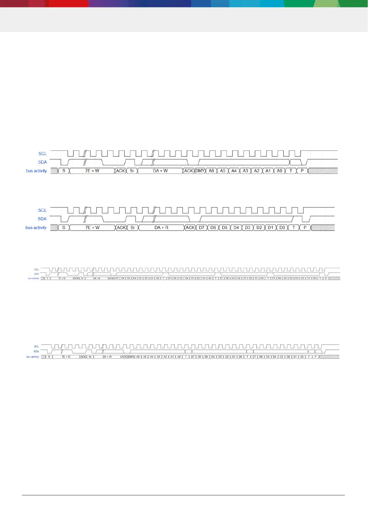
The address for all read and write transactions can be set according to the timing diagram in Figure 19. The 7-bit address
is allocated in byte section right after the dynamic address transmission. There is a 1-bit dummy content and the address
transfers from MSB to LSB.
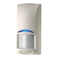
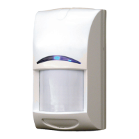
The read data transfer itself is shown in timing diagrams in Figure 20 for single byte reads, and in Figure 21 for read
bursts. Data is provided in 8-bit granularity. In both read and write operations, the data transfer bit order is from MSB to
LSB.
A read data tranfer may be followed directly by another read data transfer, without setting a new address. In this case
the automatic address increment feature of BMP581 increments the addresses for all subsequent data reads until a new
address is set.
Figure 19: I3C address setting timing diagram
Figure 20: I3C SDR read timing diagram (single byte)
Figure 21: I3C SDR read timing diagram (multiple bytes)
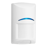
The write transaction (see Figure 22) always contains the target address before the data content is transferred. In case
multiple byte datum content are sent out by host, the internal address pointer is incremented automatically and the
content will be written into the preceding address byte by byte.
Figure 22: I3C write timing diagram
In accordance to the MIPI I3C specification, the host may skip the 7E header and start with the dynamic address section.
This applies to all I3C transactions.
5.7.5 S0/S1 error recovery
BMP581 supports S0/S1 error recovery method b) according to „Table 49 SDR Slave Error Types“ of the MIPI I3C
specification v1.1. Method a) is not supported. After an S0/S1 error, the BMP581 may stop transmitting IBIs until the
next I3C start or stop condition on the bus. Therefore, it is recommended to implement a Start-Stop sequence ( for
example by a dummy read to a device) after such an error.