Appliance information | 11
6 720 ... ... (YYYY/MM)Product Name
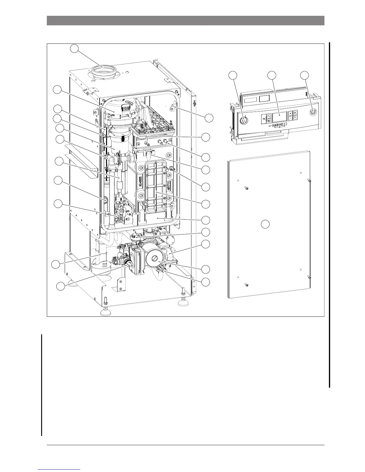
2.12 System boiler layout and components
Fig. 8 Component layout KSBR
Legend to figure 5:
[1] Flue connector
[2] ON/OFF switch
[3] Display
[4] Pressure gauge
[5] Combustion chamber cover mounting bracket x 4
[6] Flame sense electrode
[7] Electrode assembly
[8] Flow temperature sensor
[9] High limit thermostat
[10] Heat exchanger inspection cover
[11] Condensate pan
[12] Auto air vent
[13] Diverter valve assembly (only with option accessory kit)
[14] Pump
[15] Drain cock
[16] Pressure relief valve
[17] Condensate trap
[18] Gas valve
[19] Flue overheat thermostat
[20] Air Intake pipes (30 and 42kW boilers only)
[21] Manual vent
[22] Mixing device
[23] Spark generator
[24] Flue exhaust
[25] Fan
[26] Combustion chamber cover
20
1
2
19
15
14
13
12
10
11
18
17
16
9
8
7
6
25
5
24
22
23
21
43
6720809859-11.1Wo
26

 Loading...


