12 | Appliance information
Product Name6 720 ... ... (YYYY/MM)
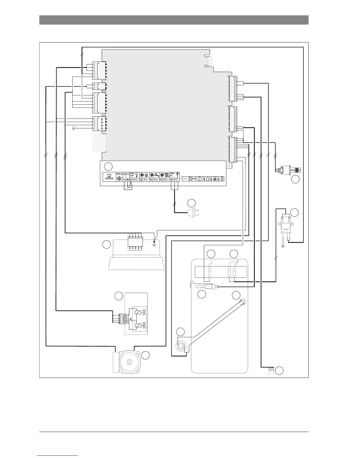
2.13 System boiler wiring diagram
Fig. 9
[1] Appliance terminal connector block
[2] Mains electrical supply connector
[3] Heat control module (HCM)
[4] Spark generator
[5] Spark electrodes
[6] Flame sense electrode
[7] High limit thermostat
[8] Flow temperature sensor
[9] Diverter valve connection
[10] Pump
[11] Flue overheat thermostat
[12] Gas valve
[13] Fan
L1
N
L2
N
N
1
13
9
3
4
2
11
7
56
8
6720809859-07.1Wo
12
10

 Loading...


