24 en | Configuration PLENA matrix
2020-12 | V1.1 |
User manual
Bosch Security Systems B.V.
7.2 Wall Control Panel DIP switch settings
The wall control panel is designed to control either the back ground music inputs or the mic./
line inputs in one specific zone. As such each wall control panel requires an ID to let the DSP
matrix mixer know which unit (or zone) is requesting a change in source or volume. This is
done via DIP IDs switches to allocate a number to the unit and its function. The DIP switches
are located on the backside of the wall control panel.
– There are two sets of IDs that give the wall control panel different functions:
1. DIP IDs 1‑8 : Line input (background music (BGM)) source selection corresponding to
output zones 1‑8.
2. DIP IDs 9‑16 : Mic./line input select and mic./line mix mode for output zones 1‑8. (e.g.
ID9 = Zone1, ID16 = Zone8).
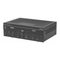
DIP switch
Wall control panel number ID
Line input (BGM) source selection Mic./line mix mode
1* 2 3 4 5 6 7 8 9 10 11 12 13 14 15 16
1 OFF ON OFF ON OFF ON OFF ON OFF ON OFF ON OFF ON OFF ON
2 OFF OFF ON ON OFF OFF ON ON OFF OFF ON ON OFF OFF ON ON
3 OFF OFF OFF OFF ON ON ON ON OFF OFF OFF OFF ON ON ON ON
4 OFF OFF OFF OFF OFF OFF OFF OFF ON ON ON ON ON ON ON ON
* Factory default.
Notice!
A DIP switch in the down position is OFF.
A DIP switch in the up position is ON.
Example:
If all DIP Switches are down/OFF this is ID1 (Factory default).
If all DIP switches are up/ON this is ID16.
Notice!
Hardware settings cannot be overruled or changed by the GUI application software.