BoschRexrothAG, RE 92802-01-B/2023-03-27
38/60 A15VSO/A15VLO series 12 | Installation
M T
2
A
S
P
X
T
1
M
A
T
3
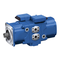
Fig� 12: Port overview A15VSO with LRDRS0 control, counter-clockwise rotation
Table 9: Ports A15VSO/A15VLO series 12
Ports
1)
p
max
[bar]
2)
State
3)
A Working port 420 O
S Suction port (without charge pump) 30 O
S Suction port (with charge pump) 2 O
T
1
Drain port 5 O
4)
T
2
Drain port 5 X
4)
T
3
Drain port 5 X
4)
CR Pilot signal (CR only)
420 O
PR Pilot signal (PR only)
420 O
H3 to H6 Pilot signal (only on H3, H4, H5 and H6)
100 O
X Pilot signal
420 O
DP, DP
1
Pilot pressure (only on DP)
420 O
M Control pressure measuring
420 X
M
A
Measuring pressure A
420 X
M
S
Measuring suction pressure (only with A15VSO)
30 X
P External control pressure
(Type code digit 8 version B or C =
with external control pressure supply)
50 O
Port P is without function
(Type code digit 8 version A = without external
control pressure supply)
420 X
1)
The measuring system and thread size can be taken from the installation drawing.
2)
Depending on the application, momentary pressure peaks can occur. Keep this in mind when
selecting measuring devices and ttings.
3)
O=Must be connected (plugged on delivery)
X = Plugged (in normal operation)
4)
Depending on the installation position, T
1
, T
2
or T
3
must be connected
(see chapter7.3 "Installation position" on page28).
 Loading...