Analog and Frequency Inputs | 11
Bosch Motorsport Vehicle_Control_Unit_VCU_Manual 61/136
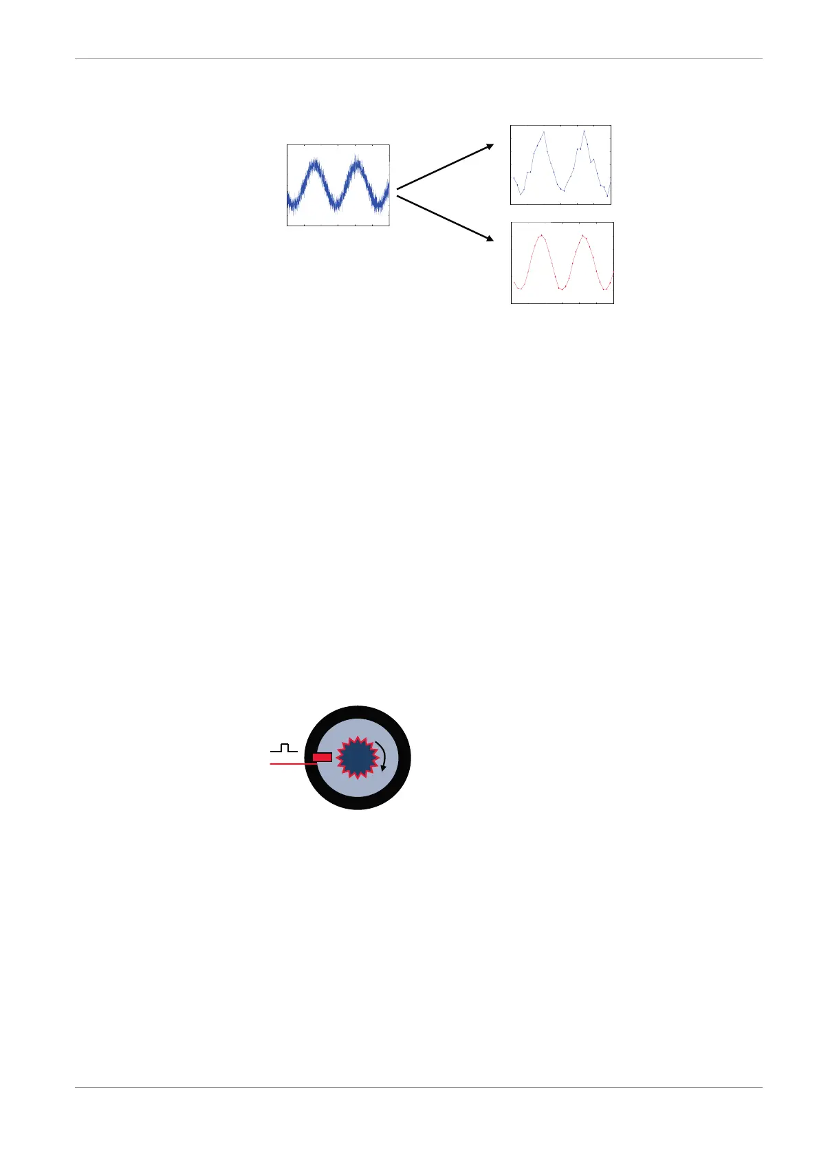
Linear phase – no signal distortion
Recorded signal 100Hz
(unfiltered)
Recorded signal 100Hz
(filtered)
Latency compensation – no filter delay in recorded data
– Filtering is (smart) averaging over several samples
– Filtered signal is delayed with respect to real time signal
– Vehicle Control Unit VCU filters have constant, frequency independent delay
– Delay (e.g. 22 samples at 10 ms) is corrected during recording
– No delay filtered vs. unfiltered in recorded data
– Correction is (of course) not possible for real time data (display, online, PWM out)
– Use filtered data for recording, use unfiltered data for real-time
11.2.6 Configuring a frequency input
Example: measurement of wheel speed
– Pulse wheel attached to wheel
– Each passing tooth of pulse wheel triggers hall sensor
– Calculation of wheel speed with wheel circumference
1. Click on ‘Measurement Sources’ in the Toolbox.
2. To expand the list of ‘I/O Channels’, click on the ‘+’ in the Vehicle Control Unit VCU
Project Tree.