29
Table 13. Bass Performance Tests
Table 12. Source Inputs to 4Ω Speaker Output
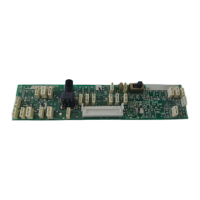
AMPLUS™ 50 TEST PROCEDURES
Note: For the following tests, set up the
unit under test as listed in the Test Setup
Notes section.
Note: Move the Amp Mode switch (S6)
from the Constant Voltage (CV) position to
the 4Ω position. This will enable the
4Ω output at J6.
Note: Place a 4Ω, 100W load resistor
across the 4Ω Speaker Output at
J6 pins 3 & 4.
Note: Refer to Table 12. Source Inputs to
4Ω Speaker Outputs for the following tests.
7. Gain Test;
Source Inputs to 4
Ω Speaker Outputs
7.1 Apply a 100mV, 1kHz signal to the
Signal Inputs at J1.
7.2 Reference a dB meter to this input
level.
7.3 Measure the output level at the Signal
Outputs at J6. It should be +14.5dBV
± 1.0dB (balanced inputs) or +35.0dB
± 1.0dB (unbalanced inputs).
8. Response Test;
Source Input to 4
Ω Speaker Outputs
8.1 Set up the unit under test as listed in
the Test Setup Notes section.
8.3 Apply a 100mVrms, 1kHz signal to the
Channel 1 and 2 Source Inputs at J1.
8.4 Reference a dB meter to this output
level at the 4Ω Speaker Output at J6.
This is the reference level.
8.5 Perform the 50Hz, 100Hz, 5kHz, and
10kHz tests as listed in Table 12. Source
Inputs to 4Ω Speaker Outputs.
Test Name Frequency Input (J1) Output (J6)
Bass, 1kHz 1kHz 31.5mV 0dBr ± 0.1dB
Bass, 20Hz 20Hz 31.5mV -4.5dBr ± 2dB
Bass, 100Hz 100Hz 31.5mV +11.0dBr ± 2dB
Test Name Frequency Input (J1) Output (J6)
Gain 1kHz 100mV +14.5dBV ± 1.0dB (balanced inputs)
+35.0dBV ± 1.0dB (unbalanced inputs)
Resp 1k 1kHz 100mV 0dBr ± 0.1dB (REFERENCE)
Resp 50 50Hz 100mV -2.0dBr ± 1.0dB (balanced inputs)
+7.0dBr ± 1.0dB (unbalanced inputs)
Resp 100 100Hz 100mV +1.25dBr ± 1.0dB (balanced inputs)
+9.5dBr ± 1.0dB (unbalanced inputs)
Resp 5k 5kHz 100mV 0dBr ± 1.0dB (balanced inputs)
+7.5dBr ± 1.0dB (unbalanced inputs)
Resp 10k 10kHz 100mV -0.25dBr ± 1.0dB (balanced inputs)
+10.0dBr ± 1.0dB (unbalanced inputs)
THD 1kHz 100mV 0.2% + 0.8%
Noise none none -50dBV + 10.0dBV