27
TEST PROCEDURES
Video Audio Tests
Note: The following tests are a subset of the
tests performed for the Music Audio tests.
The purpose of these tests is to ensure that
the I/O board multiplexer IC U3 has properly
switched the audio to the video audio input
and that the differential amplifiers have the
proper gain and bandwidth.
7. Front Channel Audio Tests
7.1 Set up the amplifier under test as out-
lined in the test setup.
7.2 Connect the signal generator inputs to
the left and right video audio inputs at J21
pins 1, 2, 4 and 5.
7.3 Issue a TV ON command (IF5). This will
cause the amplifier to change to the video
audio inputs.
7.4 Apply a 100 mV, 1 kHz signal to the left
video audio input at J21 pins 1 and 2.
7.5 Reference a dB meter to the input level.
7.6 Measure the output level at the left front
speaker output at J12 pins 3 and 4. It should
be +34.6 dB + 1.5 dB.
7.7 Apply a 100 mV, 200 Hz signal to the left
video audio input at J21 pins 1 and 2.
7.8 Reference a dB meter to the input level.
7.9 Measure the output level at the left front
speaker output at J12 pins 3 and 4. It should
be +37.1 dB + 1.5 dB.
7.10 Apply a 100 mV, 12 kHz signal to the
left video audio input at J21 pins 1 and 2.
7.11 Reference a dB meter to the input level.
7.12 Measure the output level at the left front
speaker output at J12 pins 3 and 4. It should
be +39.0 dB + 1.5 dB.
7.13 Repeat steps 7.2 to 7.12 for the right
channel, applying the input signal at J21 pins
4 and 5 and measuring the output at the right
front speaker output at J12 pins 1 and 2.
8. Digital Audio (S/PDIF) Input Tests
Test Setup:
- Connect the audio signal generator to the
input of the A/D converter.
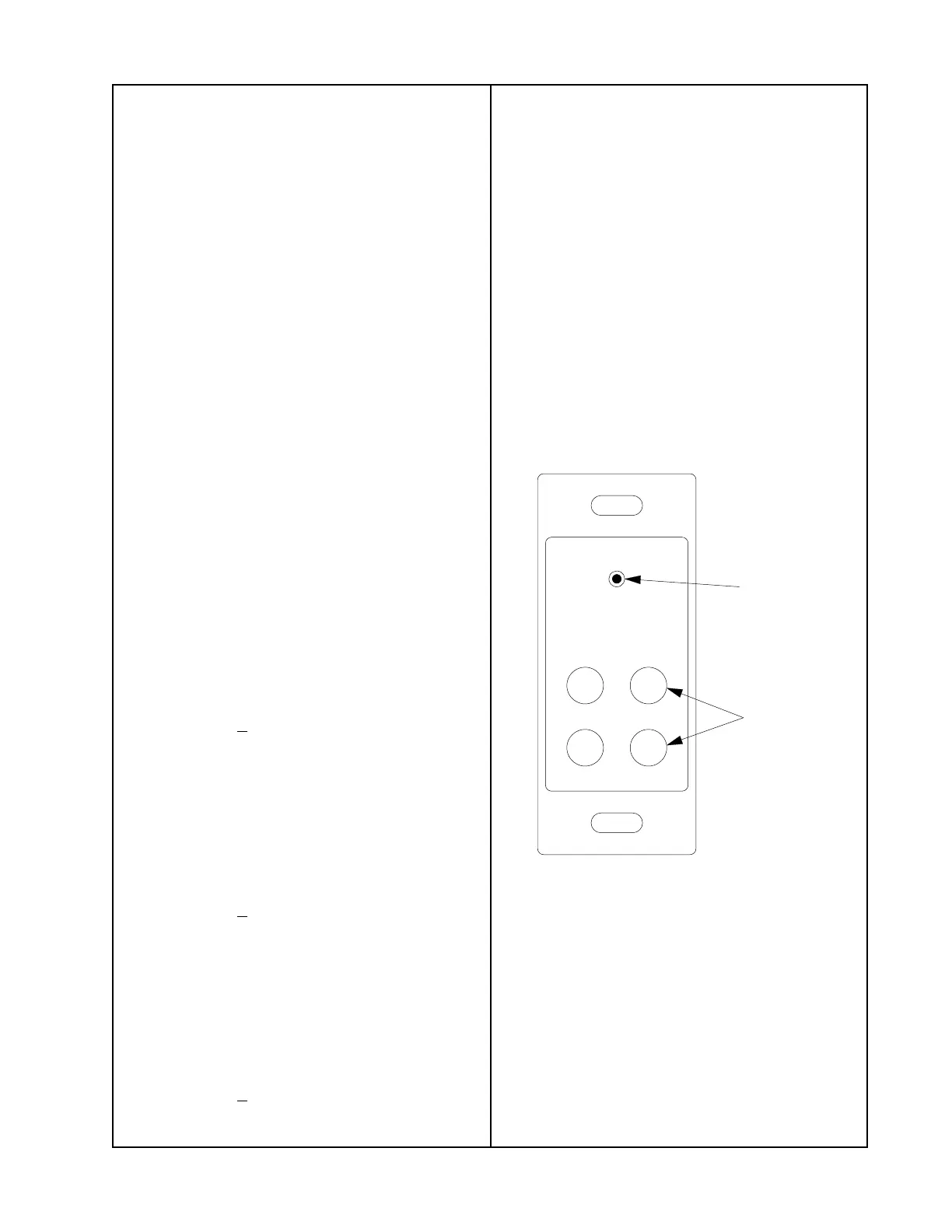
- Using the 75 Ohm video cable, connect the
output of the A/D converter to the Digital
Source 1 connector on the Digital Source
plate (see below).
- Connect the CAT-5 cable from the rear of
the Digital Source plate to the S/PDIF input
at J7 of the TA-1 amplifier.
8.1 Issue a source select VIDEO 1 com-
mand (I88) to select S/PDIF input 1 on the
TA-1 amplifier. Set the TA-1 amplifier to full
volume (issue a SmartSpeaker full volume
command [S31101] in hyperterminal, or hold
down the IR remote VOLUME UP button for
10 seconds).
8.2 Apply a 100 mVrms, 1 kHz S/PDIF
encoded mono signal from the A/D con-
verter.
BOSE
1
2
43
IR Sensor
input jack
S/PDIF digital
input jacks

 Loading...