1
CONTENTS
PROPRIETARY INFORMATION
THIS DOCUMENT CONTAINS PROPRIETARY INFORMATION OF
BOSE CORPORATION WHICH IS BEING FURNISHED ONLY FOR THE
PURPOSE OF SERVICING THE IDENTIFIED BOSE PRODUCT BY AN
AUTHORIZED BOSE SERVICE CENTER OR OWNER OF THE BOSE
PRODUCT, AND SHALL NOT BE REPRODUCED OR USED FOR ANY
OTHER PURPOSE.
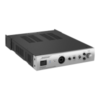
CAUTION: The Bose
®
BUILT-INvisible
®
TA-1 amplifier contains
no user-serviceable parts. To prevent warranty infractions,
refer servicing to warranty service stations or factory service.
Safety Information ............................................................................................................................2
Electrostatic Discharge Sensitive (ESDS) Device Handling .........................................................2
Warranty .............................................................................................................................................2
Specifications ....................................................................................................................................3
Speaker EQ Curves ..........................................................................................................................4
Theory of Operation ................................................................................................................... 5-21
Disassembly/Assembly Procedures ....................................................................................... 21-22
Test Procedures ........................................................................................................................ 23-30
Part List Notes.................................................................................................................................31
Main Part List, Digital BUILT-INvisible
®
Amplifier (see Figures 1, 2 and 3) ................................31
Figure 1. Input/Output PCB, DSP PCB and Chassis Exploded View .............................................32
Figure 2. Amplifier PCB Assembly with Heatsink Exploded View ..................................................33
Figure 3. Assembled Amplifier with Heatsink Open ........................................................................34
Electrical Part Lists ................................................................................................................... 35-55
I/O PCB Electrical Part List ...................................................................................................... 35-41
DSP PCB Electrical Part List ................................................................................................... 42-48
Amplifier PCB Electrical Part List ........................................................................................... 49-55
Packaging Part List, Digital BUILT-INvisible System (see Figure 4) ...........................................56
Figure 4. Digital BUILT-INvisible System Packaging View ..............................................................56
Integrated Circuit Diagrams ..................................................................................................... 57-61
Appendix.................................................................................................................................... 62-80
Accessories used with the TA-1 Amplifier.............................................................................. 62-63
CD-50 System Assembly Part List ................................................................................................63
BUILT-INvisible Series II Bass Module .........................................................................................64
SE-1 Audio/Video Switcher ............................................................................................................65
Figure 5. SE-1 Audio/Video Switcher Packing Diagram .................................................................65
CI-1 Control Integrator ...................................................................................................................66
Figure 6. CI-1 Control Integrator Packing Diagram .........................................................................66
Figure 7. TA-1 Amplifier Test Setup Diagram ...................................................................................67
Figure 8. TA-1 Amplifier Connection Diagram .................................................................................68
Table 1. Satellite Speaker EQ DIP Switch Settings ........................................................................71
Computer Setup Procedure ..................................................................................................... 72-73
Amplifier Firmware Upgrade Procedure.......................................................................................74
TA-1 Amplifier TAP Command Tables ..................................................................................... 75-78
System Troubleshooting Information ..................................................................................... 79-80
Figure 9. TS-200 System Connection Details .................................................................................81
Figure 10. TS-400 System Connection Details ...............................................................................82
Figure 11. TS-600 System Connection Details ...............................................................................83