8
THEORY OF OPERATION
Input/Output (I/O) PCB (continued)
Music Center input
J8 [A1], a four pin connector, provides a connection from a Bose
®
Lifestyle
®
music center to the
amplifier. This connector serve two functions. It can be used for connection to a Bose Lifestyle
®
music center or alternately for remote terminal access by means of an IBM compatible PC.
A table will help explain this.
In the Remote Terminal Access mode, a system installer can set up a notebook PC in the home
theater room and run Installer
TM
software to custom equalize and balance the amplifier system
for the customer’s particular home theater room. The installer would connect the PC’s RS-232C
serial output to the Lifestyle
®
connector on the Bose wall panel, temporarily disconnecting the
Lifestyle
®
music center. Switching between the two modes is accomplished via the DPDT relay
K1 [A1]. K1, shown in the deenergized state (Normal Lifestyle
®
mode), is controlled by the logic
level signal provided to pin 3 when the remote terminal is present and has activated DTR.
RS-232C input/output
The amplifier in some installations may work entirely under RS-232C control. Such installations
may have Crestron or AMX remote control devices. J9 [A2] provides for RX, TX, and ground
connections to such a terminal. Since RS-232 sources can present electrical waveforms swing-
ing between up to +/-12V, the RX signal is passed through a special RS-232C to TTL translator,
part of IC U10. In the same fashion, to permit the amplifier to transmit a bipolar TX signal, the TX
source is buffered on the way out through the output section of U10.
S4, Speaker EQ switch, and J1, Header to Test Accessory
The four signals controlled by S4 [B3] are read by the microcontroller U5 [C4] during initial
power-up of the amplifier. Refer to the Appendix of this manual for the EQ settings of S4.
J1 connects the I/O PCB with the test accessory. This connector is not used on production
amplifiers.
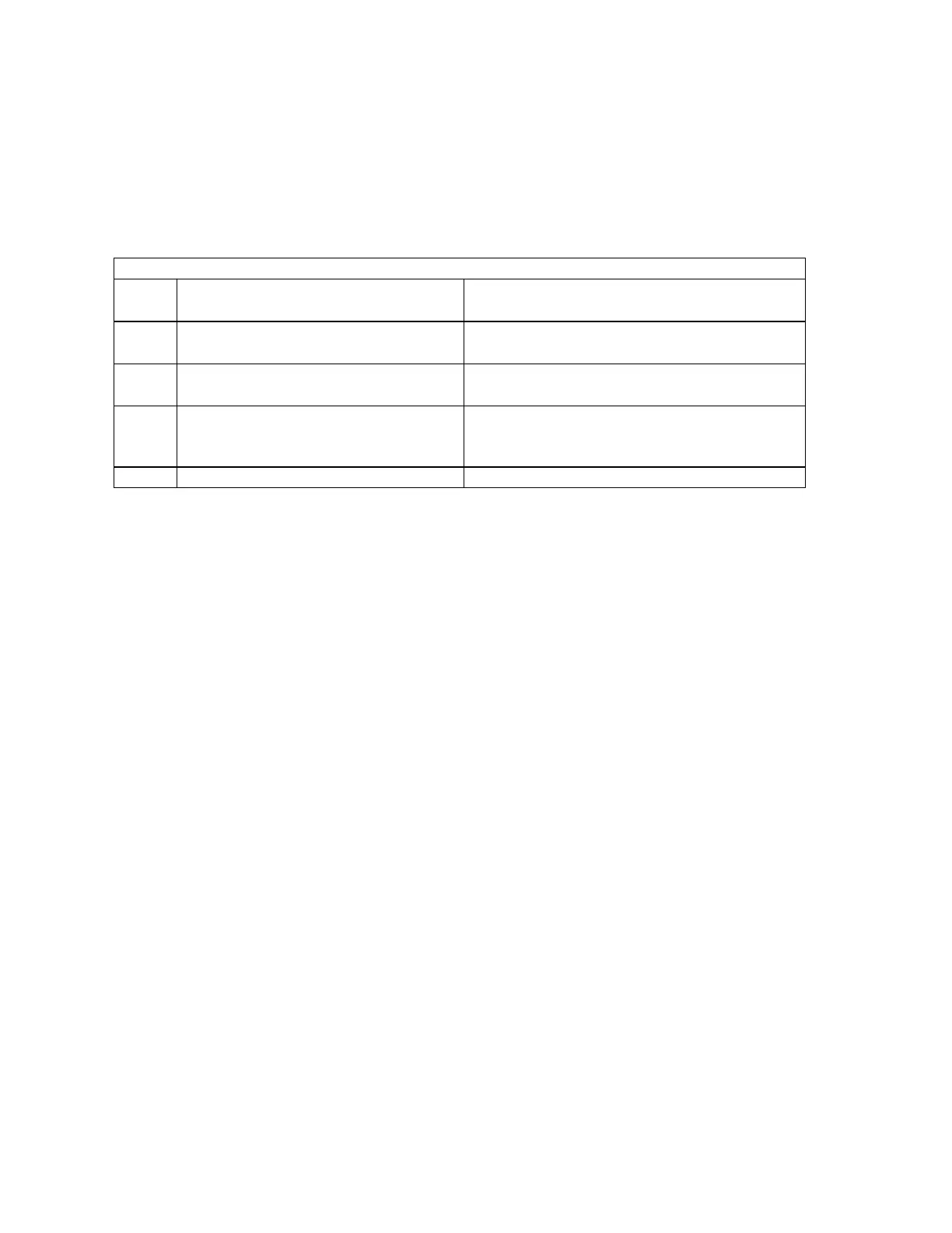
J8 Functions
J8
pin
Mode: Normal Lifestyle
connection
Mode: Remote terminal access
1
Turn_on signal from Lifestyle
to
the amplifier
RS-232 RX line, data sent from RS-232C
terminal or PC to the amplifier
2
Speaker data sent from Lifestyle
to the amplifier
RS-232C TX line, data sent from the
amplifier to RS-232C terminal or PC
3 Antenna signal DTR: RS-232C terminal or PC sets this
high to tell the amplifier to operate in the
Remote Terminal Access mode
4 ground reference ground reference

 Loading...