Pre Start Inspection and Operation
3.20
4. When the top of the attachment mounting plate (Item 1, Figure 3–28) is rmly
seated in the attachment mounting bracket (Item 2, Figure 3–28), tilt the
attachment mounting plate backward slightly to allow the lower edge of the
attachment mounting bracket to slide into place on the attachment mounting plate.
Figure 3-28 Attachment Installed
5. Shut the engine off.
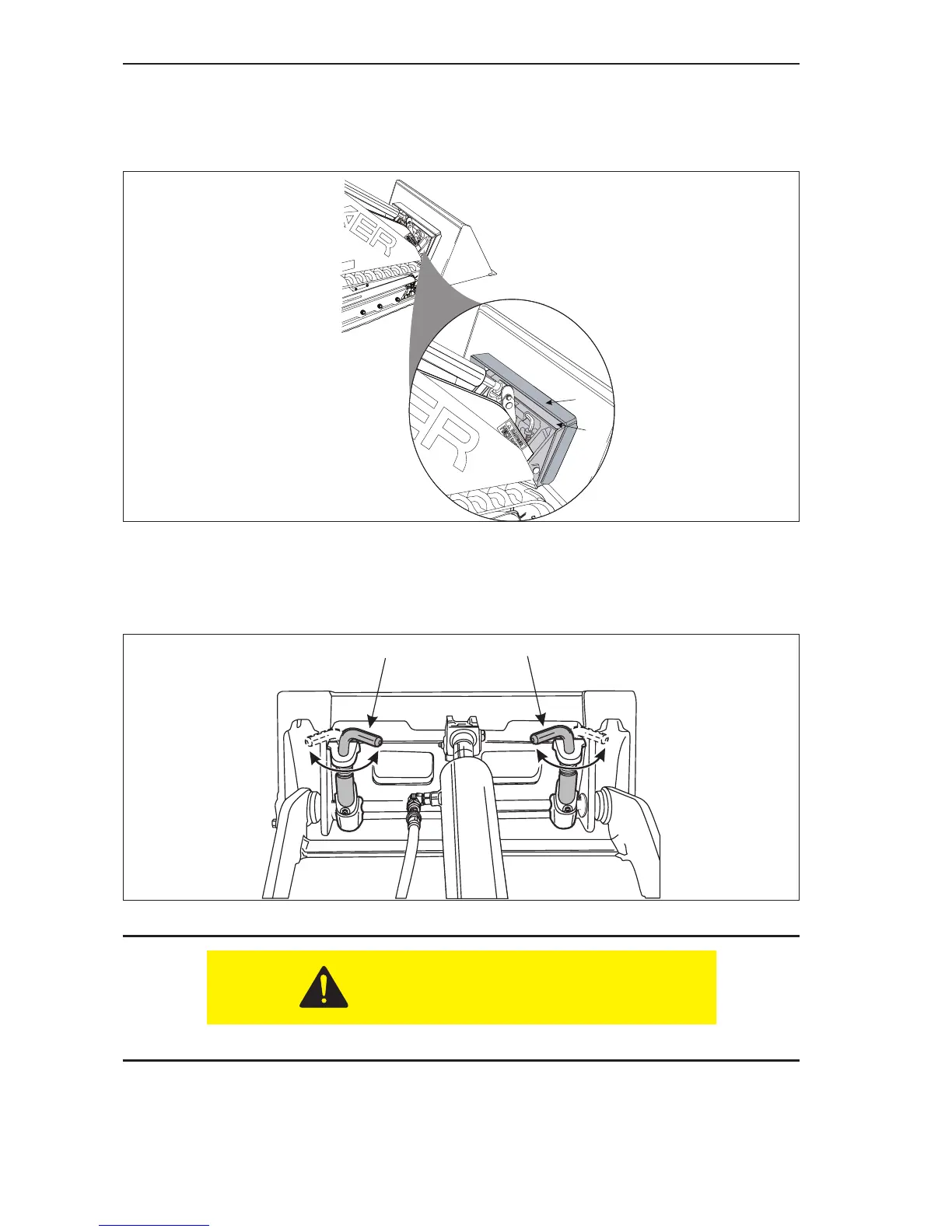
6. Rotate the attachment lock pins (Item 1, Figure 3–29) into the locked position,
securing the attachment to the machine.
Figure 3-29 Attachment Locks in Locked Position
DO NOT go underneath the attachment when it is raised.
7. Start the engine and raise the attachment off the ground. Visually inspect the
bottom edge of the attachments mounting plate to make sure that both of the
attachment lock pins are securely holding the attachment in position.
1
2